First Build - CB350 Twin

halekai

Active Member
Hello Y'all,

I guess it is my turn to chronicle a build here at DTT. I'll try and be as helpfull a a newbie can be out of appreciation for how helpfull this site and everyone on it has been to builders everywhere.

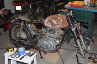
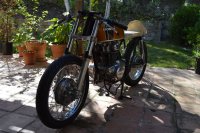
last summer I was cruising CL and found a CB750 basket case for sale. I scooped it up spontaneously not really sure what I wanted to do with it. I ended up trading the motor for 1972 CB350 K4. After selling off the rest of the 750 stuff the CB350 was essentially free. Lucky thing because it was pretty beat up on inspection (I traded it over the phone sight unseen).

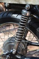
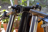
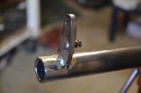
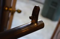
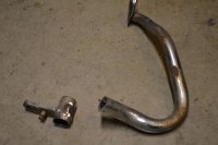
I dont think the old guy knew that his son had crashed the thing into a tree bending the forks all around and cracking the upper tree. The frame was straight so that saved me from the part out.

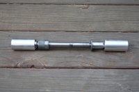
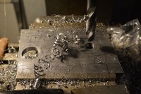
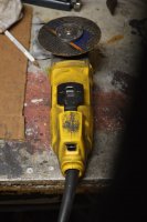
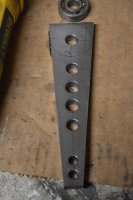
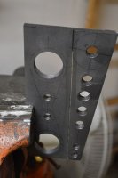
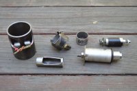
The first thing I did was get the bike running. The carbs were totally shot. Filled with aluminum oxide and a lot of the structure inside the float bowls was eaten away so that the jets did not even have anything to perch within. I located a decent set (traded for some of the 750 stuff) and after some fiddling she started right up. I did a compression test and both cylinders matched at 160 psi.

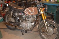
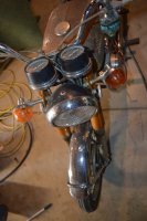
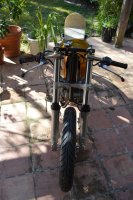
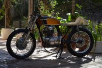
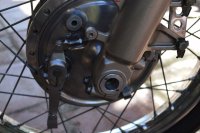
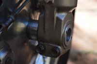
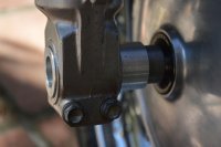
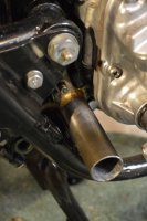
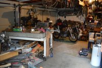
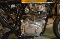
Here is a picture of what I started with...
 

Attachments

  • dtt1.jpg
    dtt1.jpg
    186.3 KB · Views: 233
My goal with this bike is to go through each system and re-work it to the best of my ability. Everything will get rebuilt or replaced but my intention is to do all of the work myself. Some of the things I am planning are...

GSXR front end
tapered steering bearings
locate and paint a period tank
fab a seat pan/cowling
rebuild the top end and polish the motor
rebuild the hubs and tune up the drum brakes
tear down and rebuild the wheels to be true and strong
de-tab the forks of anything not needed (running the original drums and not discs)
fab a set of clip on bars
rebuild and polish the rear shocks
re-wire the harness and go through all electrical components
french in a rear tail light
mod the rear fender something less gangley
chop the front fender a bit
fab up some carbon fiber velocity stacks
rebuild the clocks and tuck the headlight clock assembly inboard and low
I have not decided on rear sets or keeping stock footpegs

I should also mention that aside from gaskets, cables, tyres/rubber parts I dont want to spend any money on this project. I have budgeted $200 for tyres, whatever for powder coat and about $250-$300 for everything else.

So fast forward through the tear down, de-tabbing the frame and powder coat...

I located a nice set of forks from a 2003 GSXR for $100. Nice seals and comes complete with steering dampener which for me is a must have. $44 on tapered steering bearings from All Balls Racing and here is the test fit.
 

Attachments

  • dtt3.jpg
    dtt3.jpg
    202.3 KB · Views: 223
And here she is after powder. In testing the GSXR front end I did run into some minor issues.

I had heard that these bearing kits from AllBalls come with spacers. Mine did not. Just the two races and two bearings. The top race fit perfectly after just removing the existing Honda race. The lower race is set pretty deep...more than 1cm so I first tried to leave it in and put the new race in over it. It worked but it left me with just a few threads on the locknut up top.

I removed the lower Honda race but without a spacer the new race sits too far in and leaves the lower triple tree rubbing the head tube. I used the Honda race and ground it down to exactly 4mm. Pressed it into the head tube and then the All Balls race. Everything fit exactly as it should.

Ill leave it there for now. Next up is the motor and wheels...
 

Attachments

  • dtt5.jpg
    dtt5.jpg
    165.4 KB · Views: 217
  • dtt4.jpg
    dtt4.jpg
    163.2 KB · Views: 212
Here are the wheels after polish and rebuild. I took both hubs totally apart which was the first time I have ever really messed with drum brakes. It turns out that both sets of shoes were in great shape. I sanded and crosshatched the drum surfaces while I was in there. I cleaned and re-greesed the bearings and the whole thing was as good as new.

I also spent quite a bit of time milling the axle conversion sleeves to use the CB350 front wheel with its drum brake. The sleeves are an extremely tight press fit with threaded cotter style set screws to hold everything in place. The set screws align with the opening in the bottom of the fork to prevent any side to side movement that might happen.

I ordered some Avon road racer tyres, 110 in the back and 90 in the front. I feel like I blew my whole budget right there but baby's gotta have new shoes!
 

Attachments

  • dtt8.jpg
    dtt8.jpg
    143.5 KB · Views: 225
  • dtt7.jpg
    dtt7.jpg
    137 KB · Views: 200
  • dtt6.jpg
    dtt6.jpg
    171.5 KB · Views: 209
I have made some progress these last few days. The tyres came and I installed them. My neighbor has all of the tools so it went very smoothly.

I also refurbished the rear shocks. I took them all the way down as far as I could. One of them had no gas or fluid left and so I had to switch it out with another in my (growing) parts bin. I did the tin foil and olive oil trick to get the major rust spots and then followed that up with fine sandpaper. I also cut down the chrome covers because I like the look of the naked springs.

Another major project that is nearly complete except for the finsh work is the clip-on handlebars. I used 4130 chromo tubing from Aircraft Spruce. Mitered the bar at 10 degrees using a hole saw on the mill. Brazed on two clamps per bar and threaded those for an M8 stainless bolt. Capped the ends and fillet brazed the pieces together.

I spent a couple hours going through my controls. Cleaning them up and milling out a slot for the wire bundles to pass externally. Since these controls were designed to run the wire bundle inside the handlebars there is no place for the wires to exit like in the CB550 and 750's. I had all the little springs and plastic pieces apart and it took a while to figure out how to compress everything all at the same time inside the turn signal horn assembly.

Last step was to drill the little pin/dowel holes in the bars that keep the controls from moving.
 

Attachments

  • dtt9.jpg
    dtt9.jpg
    217.4 KB · Views: 224
  • dtt10.jpg
    dtt10.jpg
    196.9 KB · Views: 226
  • dtt12.jpg
    dtt12.jpg
    152.2 KB · Views: 221
  • dtt8.jpg
    dtt8.jpg
    208.9 KB · Views: 229
Here is a picture of the clip-ons up close and also some closeup shots of the axle conversion installed.

I also forgot to mention that I made a fiberglass seatpan. Made a mold out of sheetmetal so that I can replicate them to infinity!
 

Attachments

  • dtt13.jpg
    dtt13.jpg
    142.2 KB · Views: 221
  • dtt14.jpg
    dtt14.jpg
    117.6 KB · Views: 268
  • dtt15.jpg
    dtt15.jpg
    86.2 KB · Views: 216
  • dtt16.jpg
    dtt16.jpg
    86.9 KB · Views: 243
Now that I can at least push the thing around the garage without too much difficulty I moved my attention to seating position and rearsets. I was fully committed to using the standard footpegs and riding position but after testing out several options I just felt like the clipons combined with the decreased fork offset of the GSXR triple trees brought the hand position so far back that it made the standard footpegs very cramped.

In keeping with my pledge to spend as little as possible on this build (I only have $50 left in the budget) I decided to make my own rersets.

Last night I looked at the DTT forum on rearsets and learned a lot. I found a beautiful set but an outfit called Titan. Really beautiful metalwork. I think they are fillet brazed and chromed for the Titan 500 rearsets. His uses a cable actuation which I thought about doing as there does not seem to be an elegant solution to the CB350 rearset problem. Seems like the pipes get in the way or the kickstart or how do you engage the actuator arm? or all three.

I like the way the CB550 has the actuator arm extending outboard and so I decided to extend my actuator arm/pivot outboard as well.

It is complicated to explain but essentially the rearset will engage at the same pivot that the original brake lever used. This keeps everything backward of the rearset at factory specs and I can even use the original brake light switch. Hopefully pictures will explain everything. I have seen a lot of variations on CB350 rearsets but never this one so I am thinking this through as I go.
 

Attachments

  • dtt4.jpg
    dtt4.jpg
    117.9 KB · Views: 214
  • dtt3.jpg
    dtt3.jpg
    68.5 KB · Views: 222
  • dtt2.jpg
    dtt2.jpg
    60 KB · Views: 213
  • dtt1.jpg
    dtt1.jpg
    141.5 KB · Views: 193
Here are more pictures of the rearset progress. The rough out of the pegs and brackets. Also another shot of the pivot point and the parts all together so far.

You can see that the pivot rotates on a bushing and All I am doing is extending the arm outward.
 

Attachments

  • dtt4.jpg
    dtt4.jpg
    161.9 KB · Views: 216
  • dtt3.jpg
    dtt3.jpg
    125.6 KB · Views: 224
  • dtt2.jpg
    dtt2.jpg
    146.9 KB · Views: 209
  • dtt1.jpg
    dtt1.jpg
    138.8 KB · Views: 292
Not much progress today on the Honda. This morning I got a burr in me to totally rip apart the shop and repack everything. You know how it goes when you are in the middle of a big project and suddenly it looks like a tornado went through the place. If one of the neighbors came by they would have thought it was a crack den...so I cleaned...

I did get the brackets 90% done and I layed out the levers for the rearsets. So on with the pictures.
 

Attachments

  • dtt1.jpg
    dtt1.jpg
    134.6 KB · Views: 207
  • dtt3.jpg
    1.5 MB · Views: 234
  • dtt5.jpg
    dtt5.jpg
    196.9 KB · Views: 223
Thank You Kamn,

We will see where it leads me.

Today not much progress. A lot of distractions and I had to teach myself how to use a boring head. I scored a beautiful C.C. Craley boring head from Ebay recently and I have never used it. It is the type with high speed steel inserts and not the boring bar type. It took a while getting the bits sharpened correctly and finding the right speeds etc but in the end I was able to mill perfect press fits for the bearings on the rearsets. I am not using bushings on these. Also milled the rest of the holes and the drillium in the lever arms.

Now just cut them out, Press in the bearings, shape them, firnd the precise alignmnet, braze them together, mill the pivot, mill the footpeg, knurl the footpeg, fab the connecting rods and clevis hinges, braze in the jack shaft attachmnet arm, assemble everything and I am done!

I am including one photo of the polished motor. I kind of skipped that part. Suffice it to say that after I got the motor running I broke it down to the cases (not the cases themselves) and rebuilt everything, honed the cylinders, new rings, checked to see everything was in good repair and within spec, new gaskets and finally most of the pieces were cleaned and polished. Not a mirror finish but pretty shiny.
 

Attachments

  • dtt5.jpg
    dtt5.jpg
    152.2 KB · Views: 202
  • dtt4.jpg
    dtt4.jpg
    196.1 KB · Views: 184
  • dtt3.jpg
    dtt3.jpg
    144.3 KB · Views: 208
  • dtt1.jpg
    dtt1.jpg
    167.6 KB · Views: 213
Would love to see some pics/details on how you cut those out of that plate next. I know there's no magic - likely lots of rough cuts and then grinding / filing but would love to see it.
 
Tim, As you requested. I have extensive experience with a cutting wheel on a grinder. When I was a carpenter I would spend weeks coping crown and baseboard instead of mitering. (much faster and perfect joints) So cutting straight lines is not too much of an issue. The first thing I do is make sure the lines are bold. Then I set it up in the vise so that the cut line is vertical and the wheel will be on the right side of the cut line so I can easily monitor things. I put on a stocking cap to protect my hair from catching on fire and eye and hearing protection. On goes the fan to vent out the fumes...

I start from the bottom and let the wheel rock into place right to the edge of the cut line. Then I let the wheel climb upward in a first pass shallow cut. (shown clearly in one of the pictures) This gives me something to track as well as a visual since the heat soon obliterates any lines I draw. Then I just gently cut away making sure not to undercut my edge. Overcut is fine as you can always clean things up later.

Keep in mind that this is 10mm 3/8" cold rolled steel so it takes a while to get through it.

All told I spent 40 minutes cutting. I was able to finish before my wife got back from walking our dog!!! Thats free shop time!!! I quickly jumped outside and grabbed the broom and started sweeping the drive! Ha!

The results are great. The arms are within 1/5mm and need almost no file work. The radius on each piece will need the majority of the file work but these things dont build themselves and there is some work involved.

Ill let the pictures tell the story...
 

Attachments

  • a7.jpg
    a7.jpg
    107.8 KB · Views: 201
  • a3.jpg
    a3.jpg
    94.3 KB · Views: 207
  • a2.jpg
    a2.jpg
    129.1 KB · Views: 201
  • a1.jpg
    a1.jpg
    101.8 KB · Views: 195
The rest of the sequence...
 

Attachments

  • a11.jpg
    a11.jpg
    95.2 KB · Views: 181
  • a10.jpg
    a10.jpg
    132.8 KB · Views: 194
  • a8.jpg
    a8.jpg
    146.4 KB · Views: 181
  • a9.jpg
    a9.jpg
    103.8 KB · Views: 165
Custom CB350 tools that I made out of necessity...from left to right they are

1. Rear shock compression tool. I use a bottle jack under the shock and sandwhich this tool between the jack shock and the bottom of my bench. Compress the shock and fish out the retainer clips through the holes. Worked like a charm.

2. Valve spring compression tool. I mount the valve train in the drill press and use the arbor to compress the spring...self explainatory

3. Oil centrifuge removal tool.

4. Go No-go gauge for 32mm sealed bearing in rearsets.

5. Rear shock rubber grommet compression/removal tool. They can get pretty frozen in there and it is necessary to remove any rubber parts for powder coating.

6. Rear shock rubber grommet compression installation tool. This also doubles as an arbor to chuck up small or irregular work in the lathe.
 

Attachments

  • a13.jpg
    a13.jpg
    141.3 KB · Views: 175
Awesome stuff. I always have a vision of people with nice bandsaws whipping out complex shapes from plate steel like cutting balsa wood :)

I did coped inside corners on my 10" poplar baseboards in my house too, but I did it with a hand held coping saw. Cut it 45 degrees and then just followed the line with the coping saw. Time consuming but frankly not a lot slower than wrestling with 10" baseboards on a 12" sliding compound miter saw.
 
Loving the metal work and the lack of tools you had to use. Some good tips on how its done as well. I've just spent some time with my cutting wheel and grinder making a some bits and piece for my kz. Most of my cuts look like I've been drinking pretty heavily.
 
Thank you for the kind words Crackerman. My grinder is my best friend. Ill check out your stuff.

Tim, Off topic but next time you do any crown or baseboard, instead of using a coping saw, chuck up an abrasive disc with a plastic backing plate in the grinder and cut your 45* on the miter saw same as you would to get your line and use the grinder to backcut the cope...I use the side of a pencil lead on the edge to sharpen the line for my cutting eye. It is so fast that way you will wonder why anyone ever cuts angles, shim, glue caulk etc...its all about the compression fit.

Enough of that...on to the motorcycle. Making progress on the rearsets. I knew it would happen where I take the process that should be up to a functional standard and take it to the extreme detail. That is why everything takes me twice as long as it should. My intent was to make these quick and dirty but I will have spent as long on these as I did rebuilding the motor.

Today I milled the stage for the clevis fitting, finished all the edges, polished the arms, dry fit, brazed the pieces together, did some clean-up. The pictures tell the story. If you were wondering what the two small holes are opposite the bearing...they are to pop the bearing out if you ever need to service them down the road.

When I build another set I may opt out of brazing and drill a bolt circle to attach the arms to the spiders. I would use m3 bolts in an 8 bolt pattern and that would give me some options in configuring. It would also eliminate the need for the punch holes to pop the bearing out.
 

Attachments

  • a2.jpg
    1.8 MB · Views: 161
  • a4.jpg
    a4.jpg
    109.8 KB · Views: 164
  • a6.jpg
    a6.jpg
    200 KB · Views: 166
  • a7.jpg
    a7.jpg
    107.5 KB · Views: 166
Back
Top Bottom