Open Source DIY Electronic Ignition

Sonreir

Oregon
DTT SUPPORTER
As some of you may already know, I've been tinkering with the idea of an electronic ignition for some time. I've come to realize that I already have too many demands on my time and so I'm making the results of my work public in the hopes that you knowledgeable folks can carry on where I'm leaving off.

With that in mind, my only request is that those of you looking to make use of this information please post your results into this thread so that the community can benefit.

The majority of the work remaining is to test the code that has been written and then optimize it for use. My simulated tests have been promising so far, but I have yet to hook it up to a bike or anything of the sort...

Here's what you're going to need in your tool chest:
*Honeywell SS41 Hall Effect Sensor IC
*Some mini rare earth magnets
*PIC16HV540 microcontroller (datasheet here: http://ww1.microchip.com/downloads/en/DeviceDoc/40197b.pdf)
*20Mhz crystal oscillators (the more precise the better)
*USB PIC programmer (available on eBay for about $15, make sure it can handle a 20-pin microcontroller)
*Assorted electronics supplies like a soldering iron, circuit boards, resistors, diodes, etc (all Radio Shack kinda stuff)
*MPLAB Integrated Development Environment for your home PC (with embedded C compiler, something like HI-TECH C will work)
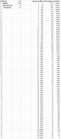
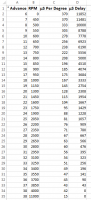
*Digital spreadsheet for calculating timing delays in the software (Excel or OpenOffice or something like that)

Parts for this project should run between $10 and $20, but expect to spend a lot of time on it. You need to modify the points plate and advancer (or, even better, get a rotor fabbed up), solder a bunch of stuff, flash the microcontroller, install and configure software on your PC... etc, etc, etc.


More to come in the next few days...

EDIT:
I've changed some of the hardware requirements as this project has progressed. I've abandoned the PIC in favor of an Arduino setup. The hardware has been a lot easier to work with and the code libraries for the Arduino have greatly simplified the necessary tasks.

The Hall Effect sensor that is being used for this project has been swapped over to an Allegro A1120LUA-T. No need for the chips, programmers, or oscillators (all this is handled on-board by the Arduino setup). The development environment I'm now using is Atmel Studio and the open source program Sketch. The Arduino Uno is about $20-$30 and plugs right into your PC via USB. You'll still want the magnets and assorted electronics components, however.
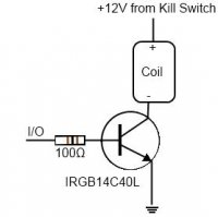
 
To begin with, you're going to need one of the attached circuits for every coil on your bike.

The purpose of the diagrammed circuit is to provide EM flyback protection to the microcontroller. Under normal operations, every time your coil is fired, tens of thousands of volts travel along the HT lead (aka plug wire) to the spark plug. These voltages are high enough to jump the gap in the plug and create a spark. Common knowledge. What isn't commonly known is that several hundred volts are also discharged from the primary coil back up the points wire to the point that fired the coil. In the standard Kettering design, the condenser (basically a large capacitor) helps to absorb some of this voltage and prevent your points from wearing out too soon. No such option when dealing with digital electronics as the voltage levels are still too great. What we have to do, instead, is create a high-voltage one-way system to allow the coil to still be trigger but also prevent any flyback from cooking our transistors and microcontroller.

Interestingly enough (well, to me, at least), this same circuit can be used to create what is known as a "points saver". Instead of triggering the coil's connection to ground directly, we can put this circuit in between and simply use the points as a switch that controls a transistor. The transistor then takes care of the heavy lifting of switching the coil. Kinda of like a solid state relay.

The IRGB14C40L is an integrated circuit specifically designed for triggering ignition coils. You'll find it in use in almost all vehicles that utilize a system of one coil pack per spark plug. They're not super-easy to find and prices do vary from $2 per chip all the way up to $15 or so.
 

Attachments

  • 422009_10150649352380159_725706417_n.jpg
    422009_10150649352380159_725706417_n.jpg
    9.9 KB · Views: 5,949
Hey Sonrier, it's the same situation with me. Too much time is needed to proto the code. On top of that, we are both using different micros (Atmel vs Pic). I may get to it eventually but now I am working on a new project (cb350). It will be double the signals for a twin. I have the basic code working for a single (only on the bench) but I still have to proto the hardware to see if it works real time. I do have a bunch of PIC micros (16F73) but the code will need to be modified for micro (pinouts and header files). So, last posting was a standstill due to time and differences in hardware.
 
eyhonda said:
Hey Sonrier, it's the same situation with me. Too much time is needed to proto the code. On top of that, we are both using different micros (Atmel vs Pic). I may get to it eventually but now I am working on a new project (cb350). It will be double the signals for a twin. I have the basic code working for a single (only on the bench) but I still have to proto the hardware to see if it works real time. I do have a bunch of PIC micros (16F73) but the code will need to be modified for micro (pinouts and header files). So, last posting was a standstill due to time and differences in hardware.

Yup, yup. I got my code working for a single as well (in my IDE, of course), but then I decided to change it to work for a 180° twin and fucked it all up. Got it sort of working, but resolution wasn't as good as I was hoping and I still need to go back and fix everything up again. My current design is to use one microcontroller per circuit and avoid all the headaches of different timings for different cylinders. That was I can stick with a programmable dwell and not have to worry if my timing is drifting at higher revs due to my microcontroller's inability to keep up with the calculations at those speeds. I have some optimization to do in my code for sure.
 
To insert it in between the points and the coil will require inverting the points signal. The points are "active low" signals, meaning they are at ground level when firing the coils. But this is out of scope of this thread.
 
eyhonda said:
To insert it in between the points and the coil will require inverting the points signal. The points are "active low" signals, meaning they are at ground level when firing the coils. But this is out of scope of this thread.

Yup. Good catch.
 
Next step is to calculate the RPMs are which each step in ignition advance will occur. For my own purposes, I used a range from 6° to 38° of advance. One of the nice things about having an electronic ignition is that you can use multiple slopes and/or functions for this purpose.

For my own bike, I know I need a lot of initial advance to help out the throttle response because I'm running lumpy pistons and a high duration cam. But the downside of running high initial advance is that starting the bike is a royal pain in the ass. Given the situation I'm working with, I've decided on 6° of advance at anything less than 400 RPM and ramping up to 18° of advance at 1000 RPM.

Time to generate a formula for that desired change in advance.

Slope/intercept form for a line is y=mx+b. y is our RPMs and x is our advance. First thing to do is figure out m. We can do this because we know the starting and stopping points for both x and y. Expressed as points on a graph, our starting point is (6,400) and our ending point is (18,1000). Slope is defined as the absolute value of y1 - y2 divided by the absolute value of x1-x2. This gives us abs(400-1000) / abs(6-18) or 600/12. Simplify and m = 50. At this point, we have enough information to solve for b. Going back to y = mx + b, we can substitute 1000 = 50*18 + b and arrive at the conclusion that b = 100. Our formula for calculating RPMs between 400 and 1000 RPM is now y= 50x+100.

After 1000RPM, I want the slope to change again, so a new formula is needed. I want to maintain a linear ignition advance from 1000 to 4000 RPMs with my total advance at 38° once I hit 4000 RPMs. Repeat as before using the two points (18,1000) and (38,4000). We get y= 150x-1700.

Armed with all the formulas you need, it's time to enter the appropriate data into your spreadsheet. Setup a column that lists all the degrees in your advance. In my case, I started at six and ended at thirty eight. In the next column, paste in your formulas such that you're calculating the RPMs at each degree of advance. next, setup a third column to calculate the total number of µS (microseconds) that elapse for every degree of rotation of the engine at the given RPM. The formula for this is "µS Per Degree =1/(RPM/60*360)*1000000". Finally, we need a fourth column to calculate the number of µS to delay in order to achieve our desired level of advance. The formula is "µS Delay = (Total Advance - This Advance) * µS Per Degree".

Your final result should look something like the attached image.
 

Attachments

  • timing.png
    timing.png
    14.8 KB · Views: 4,982
You can avoid the risk to your pic by using an ignition module (FET and coil in one package). Those are switched with a simple ground.

Have you looked at the Mega/MicroSquirt circuitry? They have the ignition nailed down pretty well. Very few failures except in overzealous COP users.

-Deek
 
ILoveThumpers said:
Have you looked at the Mega/MicroSquirt circuitry? They have the ignition nailed down pretty well. Very few failures except in overzealous COP users.

Yup. Microsquirt is what I'll be using for my EFI conversion.

VonYinzer said:
Where do the greasy wrenches come into play ;)

Anytime you want. Results may vary.
 
something doesnt look right. check your usec per deg column. i plugged it in my spreadsheet and that column is usec per rotation.
 
eyhonda said:
something doesnt look right. check your usec per deg column. i plugged it in my spreadsheet and that column is usec per rotation.

Yup. Error found and fixed. New image uploaded.
 
Much better! Ok, is our brains starting to hurt now?! Now, what is your overall control strategy? My strategy was basically the input is the HE sensor for RPMs and the output is the coil drive circuit. The input is connected to an interrupt pin. This counts or measures the time between (interrupt) pulses to determine the current RPM, based on usec per rotation (one pulse per cam rotation). Say this is X. Using a lookup table, if the RPM is in range Y, delay is Z amount. I wait X-Z seconds then pulse the output. This delay is actually the advance for the 3rd incoming pulse, not the first 2 pulses. The first 2 pulses are needed to determine the rpm. I don't have my code with me today, but I'm pretty sure this is what I did. I used a function generator for the RPMs and a scope to check the outputs. I'll post pics and more info as I get back into it.
 
eyehonda, it's probably better practice to program a default advance and wait until RPM rises over a given threshold before looking to the table. This is especially important for hard-starting and kick-start bikes, as the RPM will vary wildly during cranking/kicking. Also, at idle, you want the ignition timing to be rock solid even if there's fuel problems causing surging.

Think about mechanical advance ignitions; they have a base timing that doesn't change until well above idle.

Just a suggestion. Feel free to ignore!

-Deek
 
eyhonda said:
Much better! Ok, is our brains starting to hurt now?! Now, what is your overall control strategy? My strategy was basically the input is the HE sensor for RPMs and the output is the coil drive circuit. The input is connected to an interrupt pin. This counts or measures the time between (interrupt) pulses to determine the current RPM, based on usec per rotation (one pulse per cam rotation). Say this is X. Using a lookup table, if the RPM is in range Y, delay is Z amount. I wait X-Z seconds then pulse the output. This delay is actually the advance for the 3rd incoming pulse, not the first 2 pulses. The first 2 pulses are needed to determine the rpm. I don't have my code with me today, but I'm pretty sure this is what I did. I used a function generator for the RPMs and a scope to check the outputs. I'll post pics and more info as I get back into it.

My approach is not dissimilar. I might be splitting hairs, but I used arrays (one for RPMs and one for µS duration) instead of lookup tables to keep things fast. My first attempt had the values being calculated, but the calculations were taking too much time, so lookup tables it is!

In my design, the pickup would be physically located around 180° BTDC to allow for dwell time as well as the desired delay (more on that in an upcoming post).

Each rotation of the cam, an interrupt is triggered by the hall sensor that kicks off a function that then saves the current duration into a "last duration" value. The function then resets the clock for the current duration and makes use of the last duration value for further processing. Instead of using a direct lookup, I maintain a value in memory that tracks the current index in my array as well as the maximum value for the index.

If the duration is shorter than the value in the maximum index in the array, then nothing else happens; we're at redline and the coils don't fire until RPMs drop again. If the duration is shorter than the duration in my array at index+1 then index= index + 1 and I use the duration at the new index. If the duration is longer than the duration in my array at index-1 then index = index-1 and I use that one. Worst case scenario is only five comparisons and worst case only occurs when we're off the throttle, so I'm hoping this is quick enough processing.

This algorithm essentially only changes the possible duration by one index per rotation, but that'll be good enough for this process. The nice thing about this approach is that we don't need an initial rotation to calculate duration. The value we use at index zero will be close enough to fire the first time the hall sensor is triggered and after that we have a duration to go by.

Now armed with the correct delay duration, we spin processor cycles until the appropriate delay has been achieved. Then ground the coil to begin the dwell period, spin more processor cycles for the dwell time, then unground the coil to trigger the spark. Repeat until the engine is turned off.
 
OK... so what we have so far in the spreadsheet is useful as an exercise and/or starting point, but it doesn't tell the full story. The reason for this is that we're missing a very important piece of the puzzle. The piece is called, "dwell".

Dwell is the amount of time that the coils remain grounded and is a pretty important number. The amount of dwell determines many number of things and being able to set dwell is one of the great reasons for using an electronic ignition. The two primary things that dwell affects are the strength of the spark and the power consumption of the coils.

In a Kettering (points) setup, dwell is almost always a function of the point gap and slope of the points lobe on the cam. Once set, dwell corresponds to a number of degrees of rotation of the cam. This means that as engine speeds increase, dwell decreases. This is not desirable because setting dwell too long draws more current and so your bike ends up using up more electricity at lower RPMs. Furthermore, if the dwell is too short, your bike may not generate a big enough of a spark at higher RPMs. Combined with points bounce often seen at higher RPMs on a Kettering system, short dwell times become a big problem.

Finally, by design, the coils on your bike are probably too big for their application. This because small coils are more prone to failure when constant current is passing through them. As mentioned above, longer dwell at low RPMs causes the coils to use more power and so the coils need to be large enough to handle the current they'd see when running around at low RPMs for a while.

An electronic ignition cures more of those ailments because we can choose a static, time-based, value for our dwell rather than rely on degrees of rotation like in a Kettering system. We can achieve a strong spark at high RPMs, avoid sucking too much power from our bikes at low RPMs, and possibly swap over to smaller coils because they no longer need to be capable of absorbing the heat associated with long dwell times.

So... time to tweak the spreadsheet again.

We'll need to choose a value for our dwell setting. I've gone with 1500µS (or 1.5 milliseconds) as a starting point. Depending on your setup you may need slightly longer or shorter. The best way to determine this is to tweak the setting after you get your bike running. The shorter the dwell you can use, the better. Generally speaking, smaller coils with lower resistance will allow for shorter dwell than larger coils with high resistance. Remember though, low resistance coils also consume more wattage.

Aside from a setting for dwell, we'll also need to know our total advance (in degrees) and the desired redline for our bike (in RPMs). This example will use an 11,000 RPM redline and 38° of total advance. These values need to be used so we know where to set our electronic ignition's pickup such that we have enough time to register a "hit" on the hall sensor, ground the coil to begin the dwell, and then unground the coil to fire the spark.

To calculate this number, we use the following formula: EI setting = Dwell in µS/(1/(Redline in RPM/60*360)*1000000)+Total ignition advance in °

So EI setting is 150/(1/(11000/60*360)*1000000)+38 which results in 137° BTDC. This means our hall sensor will need be located in such a manner that it senses the magnet at approximately 137° Before Top Dead Center for the cylinder it will be firing.

Armed with this information, we need to further adjust our spreadsheet to account for our new starting point and also to allow for our dwell time. Our new formula for determining our delay time becomes the following:

µS delay = (EI advance setting - desired advance) * µS per degree - Dwell

For 1000 RPM where my desired advance is 18°, the formula looks like this:

18333 = (137 - 18) * 167 - 1500

Ensure you have enough cells in your spread sheet to cover everything from zero RPM to redline. For RPMs that fall outside your functions (mentioned in a previous post), use increments of 50 RPM and maintain the timing advance as the desired value.

Your spreadsheet should now look like the attached image.
 

Attachments

  • timing.png
    timing.png
    37.7 KB · Views: 852
Lookup tables will need less processor cycles (depending on processor). Good point about redline. I also implemented redline function but without arrays (simple if then). Did you calculate the error? Each loop is an even number of time (if that makes sense) based on your oscillator. Take that number of loops to determine the actual time delay and compare to the delay desired. The error was small (less than 1%) in my case. This will help you optimize your clock. You may find going slower may not be much worse in error but going too fast means lots of looping/counting and possible overflow (16 bit max is about 32000). I was able to do my code using an 8Mhz clock, although the resolution is just enough. I'll double check it later. Also, I forgot about dwell. My current code just pulses the output to trigger the spark. I'll have to include it on my next change.
 
My original attempt was not too good as far as accuracy went. That's what drove the decision to switch to a 20Mhz chip. Should be pretty darn good now, but tests will tell for sure.
 
And here is the code for the microcontroller to run the whole darn thing:

Code:
//INCLUDES AND DEFINITIONS
#include "htc.h"
#include "pic16f88.h"

//CONFIGURATION
__CONFIG(FOSC_XT & WDTE_OFF & PWRTE_ON & CP_OFF);

//DECLARATIONS
unsigned short RPMS[] = {2400000,1200000,800000,600000,480000,400000,342857,300000,266667,240000,218182,200000,184615,171429,160000,150000,141176,133333,126316,120000,104348,92308,82759,75000,68571,63158,58537,54545,51064,48000,45283,42857,40678,38710,36923,35294,33803,32432,31169,30000,28235,26667,25263,24000,22857,21818,20870,20000,19200,18462,17778,17143,16552,16000,15484,15000,14545,14118,13714,13333,12973,12632,12308,12000,11707,11429,11163,10909};
unsigned short DELAYS[] = {435167,216833,144056,107667,85833,71278,60881,53083,46648,41500,37288,33778,30808,28262,26056,24125,22422,20907,19553,18333,15601,13500,11833,10479,9357,8412,7606,6909,6301,5767,5292,4869,4489,4145,3833,3549,3289,3050,2829,2625,2382,2167,1974,1800,1643,1500,1370,1250,1140,1038,944,857,776,700,629,563,500,441,386,333,284,237,192,150,110,71,35,0};
unsigned short DWELL = 1500; //microseconds of dwell to be used
unsigned short MAX_INDEX = 67; //number of indices in the arrays
unsigned short advanceIndex = 0; //our current index in the arrays
unsigned short currentCount = 0;  //running total of elapsed microseconds since the last time the hall sensor was triggered
unsigned short lastCount = 0; //the elapsed microseconds of the last rotation
unsigned short setDelayFlag = 0; //indicator as to whether or not the 

//FUNCTIONS
void SetAdvanceDelay()
{
	//save the number of microseconds since we last triggered the coil and then reset the timer and flags
	lastCount = currentCount + TMR0;
	TMR0 = 0;
	currentCount = 0;
	setDelayFlag = 0;
	
	if(advanceIndex < MAX_INDEX && lastCount < RPMS[advanceIndex + 1]) //current rpms exceed the next stepping point for ignition advance
	{
		advanceIndex = advanceIndex + 1; //next delay will be shorter because we're increasing in RPMs
	}
	else if (advanceIndex > 0 && lastCount > RPMS[advanceIndex - 1]) //current rpms have dropped us down in ignition advance
	{
		advanceIndex = advanceIndex - 1; //next delay longer because we're decreasing in RPMs
	}
	//else {}  RPMs haven't changed enough to cause and increase or decrease in delay
}

void MicroDelay(unsigned int us)
{
	while(us--) //while the delay period is not zero, set the delay period = delay period - 1
	{
		;  //NOP
	}
}

void DwellAndFire()
{
	MicroDelay(DELAYS[advanceIndex]); //wait for the determined delay period
	
	RB1 = 1;  //ground the coil
	MicroDelay(DWELL); //wait the dwell period
	RB0 = 0; //trigger the coil by ungrounding it
}

void main()
{
	INTCON = 0b11110000;  //global interrupt enabled, peripheral interrupt enabled, TMR0 interrupt enabled, RB0 interrupt enabled
	OPTION_REG = 0b11001000; //RBPU on, INTEDG rising edge, TMR0 external osc, TMR0 rising edge, TMR0 prescaled to zero
	TRISA = 0;	//port A to output
	TRISB = 1;	//port B to input
	RB1 = 0;	//unground coil
	TMR0 = 0;	//reset timer

	//program in loop until power off
	while(1)
	{
		if (setDelayFlag == 1) //hall effect sensor has been triggered
		{
			SetAdvanceDelay();
			
			if(lastCount > RPMS[MAX_INDEX]) //not past redline, OK to fire the coils
			{
				DwellAndFire();
			}
		}
	}
}

void interrupt isr()
{
	if(INTF)	//RB0 external interrupt (hall sensor)
	{
		INTF = 0;	//clear external interrupt flag
		setDelayFlag = 1;
	}
	else if (TMR0IF) //timer interrupt, increment the number of microseconds
	{
		TMR0IF = 0;
		currentCount += 256;
	}
}

Before I go explaining the algorithm behind it in any greater details, there are a few caveats to be aware of:

1.) This code was originally written and tested for the PIC16F88 microcontroller but I've made a recent decision to swap over to a PIC16HV616 as it supports 12V, natively, without the need for a voltage regulator. A 32 bit timer is gained as well, which could be useful.
2.) Because of the change in microcontroller, my includes are incorrect and I'm pretty sure the configuration sections need to change, too.
3.) All the delays are currently listed in µS, but this will almost definitely need to be translated to processor cycles. There is a relation between µS and processor cycles (at 20Mhz clock speed, you get five cycles per microsecond), but I'm not accounted for any of this just yet. My rough guess is that calling the MicroDelay() function will take around five cycles just to call it (before it starts any delays at all). Each iteration of the "while" loop, I think, will take four cycles. So multiplying our delay periods by .8 should get us closer to the mark on the actual delay in µS.

The Algorithm
For those of you unfamiliar with the word, "Algorithm", it's basically a recipe for solving a problem or calculation. Algorithms are often listed in plain language so as to be easier to understand. They need to be easy to understand because the code that implements the algorithm isn't always easy to understand and having a recipe nearby can make following the logical processor a lot easier.

So... here's how it all works:

We'll need to physically hook up a magnet and the hall sensor to the crankshaft. As your engine rotates, the magnet should pass the sensor and trigger the Hall sensor. The sensor then sends the signal to a pin on our microcontroller The pin on the microcontroller is what is called an "interrupt" pin. When the microcontroller gets a signal on this pin, it's stops what ever it's doing to respond. In the code above, this is the void interrupt isr() function.

So every time the Hall sensor is triggered by a rotation of the cam, the isr() function will reset the the INTF (interrupt flag) so that we have the opportunity to trigger the interrupt again (failure to reset this flag may result in only the first triggering of the Hall sensor to be detected and subsequent triggerings to be ignored). Additionally, we set the setDelayFlag variable equal to one. By design, very little code should operate within the interrupt section. Remember, the interrupt section is stopping all other operations, so keep it short and simple.

Also within the interrupt function is a handler for the timer interrupt. The internal timer in the chip will raise an interrupt every time it counts off 256 µS. We add that into our current count so we can track how many total µS have occurred since the last rotation (more on that later).

OK... so with our interrupt defined, lets take a look at the void main() function. main() is the function that is called by the chip after it powers on and takes care of the configurations and declarations portions. After handling some configuration values, you can see that main() immediately jumps into a "while" loop. A while loop instructs the processor to continue performing a specific task so long as certain condition holds true. What is defined as "true" is any value that isn't equal to zero. So in this case, our while loop will continue to run forever (or at least as long as the processor still has power).

Inside the while loop, all we're doing is checking to see if the setDelayFlag is equal to one. As you recall, it's our interrupt function's job to set this flag, and so our while loop will just sit and do nothing (very, very quickly) until we receive a signal from the Hall sensor.

Once that signal has been received, the magic happens. The main() function, having now detected that the setDelayFlag is equal to one, will call a sub-function named void SetAdvanceDelay(). SetAdvanceDelay() will store the last result of of our counting operations (the one that times to see how long it took for our cam to complete a rotation), and reset all of our counting and flag variables so that the hole process can begin again after the next rotation.

After the variable resetting has occurred, we do a couple of comparisons. The first comparison tests to see if our RPMs have increased enough that we need to go to the next "line" in our Excel sheet for timing advance and delays. The second comparison (which only occurs if the first comparison wasn't true), checks for the opposite condition; whether the RPMs have dropped enough that we need to increase the delay and/or retard the timing. If either of these conditions are true, then we change the index in our array to provide the next higher or next lower value within it. At this point, the sub-function call is complete and control of the microprocessor is returned to the main() function.

Back in main(), you can see the next line after our call to the SetAdvanceDelay() is a check to see if we've exceeded our predefined Redline value. This check ensures that our current index is less than our MAX_INDEX. The MAX_INDEX value is equal to the number of items in our array, and so if we're reached the end of the array then we know we're at redline.

Provided we're not at redline, we're OK to fire the coil and generate a spark to keep the engine going. This is all handled in the void DwellAndFire()function.

Upon entering the DwellAndFire() function, the first thing we do is to wait out our predetermined delay period for our desired advance and measured RPMs. This is done by calling the MicroDelay() function and passing in the number if µS we want to wait.

Inside MicroDelay(), we cause the processor to "spin" some cycles (do nothing until a condition has occurred). So long as our delay is not zero, we subtract one from our delay and then check and see if it's reached zero yet. After the delay value has reached zero, we exit the function and return back to DwellAndFire().

Back in DwellAndFire(), the next line of code sets one of the output pins of the microcontroller to "on". This then triggers the IRGB14C40L which completes the ground from the ignition coil. The coil is now charging up.

The next line of code now calls another delay, but instead of using the delay based on our ignition advance and RPMs, we use a set delay of 1500µS (which is our dwell period). After the dwell period has expired, we set the output pin of the microcontroller to "off", which breaks the ground of the coil and causes it to fire a spark into the cylinder.

The DwellAndFire() function is now complete and control of the processor returns back to main(). At this point, the iteration of the while loop within main() has completed and it starts over again, ad infinitum. Main() will continue to loop in circles until the interrupt is trigger by the hall sensor.
 
Back
Top Bottom