Follow along with the video below to see how to install our site as a web app on your home screen.
Note: This feature currently requires accessing the site using the built-in Safari browser.
We noticed you are blocking ads. DO THE TON only works with community supporters. Most are active members of the site with small businesses. Please consider disabling your ad blocking tool and checking out the businesses that help keep our site up and free.
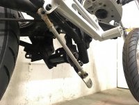
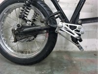
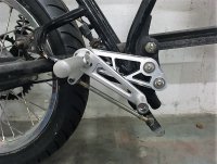
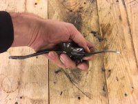
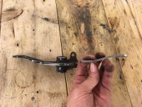
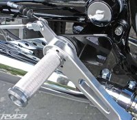
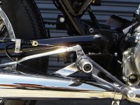
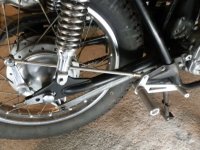
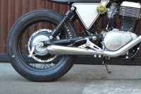
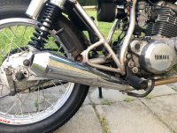
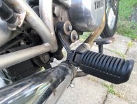
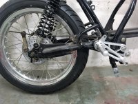
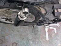
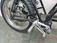
Been scratching my head over the brake linkage over the weekend. I could get this set up to work really well I think (the pictures don't show what the optimal/final angles would be) but I am not sure I want to go down this path... It seems to add a lot of weight and complexity to the bike and operation. If I went with a direct connection the the brake arm I could remove the bracket under the frame and lose some weight there, plus the pivot shaft and the steel bracket that I would weld up (mocked up in the images).
So back to a few posts ago... How poorly would a direct connection perform? I know @irk miller wondered the same thing. It also seems there have been people before me have done this and succeeded. Even Ryca with their cafe racer kit for the LS650 Savage do it - post to follow.
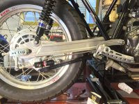
Failing this as an alternative, I have one other option. That would be to design a bracket that rotates around the swingarm pivot itself. I would draw up a bracket to be machined in aluminium that goes over the swingarms welded pivot shaft. Might need to let this brew in my head for a while.
Just to through another spanner in... Have you thought about using a hydraulic slave cylinder to pull the rear brake actuator and a small master up near the reset? Might weigh similar to all the steel there for the stock setup.
We used a similar linkage on our first CB160 Vintage race bike. It worked fine but too complicated by far. So then we moved the cable mount and used a straight cable run.
In fact there is a cable conversion for the RD350 that looks like it would be perfect for your needs without reinventing the wheel.
Yeah through my searches I came across the following set ups... Hydraulic set us included. This is one of the cleanest I have seen. Then there is a budget version I saw as well - probably works just as good, just looks a little ratty.
Has anyone tried the DCC kit? https://www.dimecitycycles.com/dcc-customs-rear-brake-cable-conversion-kit.html
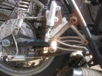
The direct mechanical linkage is fine, but I don't like the bends in the linkage rods. The more force you apply the more you're going to lose to that bar straightening out instead of applying your brake.
The rod is supposed to be in tension, so when it's a straight rod it applies the full pressure to the brakes. When bent like that sure it clears the exhaust but the forces are all wrong, you're trying to straighten the rod and apply the brakes at the same time. Worst case is in a panic you stomp the brake and the rod just straightens out, the next time you apply the brakes you don't have any.
Same goes for using the rod to "push" the brakes, it works and I see it done, but in a panic it's going to bend and you're screwed.
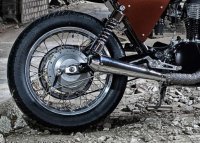
That TZ rear wheel that Irk posted is the tidiest and more or less how I set up an R5/RD350 rear brake. I had the rear brake plate welded to create an abutment for the cable rather than making a steel one to bolt on and I used a Suzuki T500 or GT750 cable. That was on a TD3 so it already came with cable ends at the front.
Note that with the pull to the bottom, if anything should happen to your stay rod, the drum will rotate pulling the rear brake into full lock. Not fun at 65 mph on Folly Beach road!
I looked really hard at the DCC kit and almost bought it. But after watching their video about it: https://www.youtube.com/watch?v=M0PnjaZJicQ
I decided not to. It is really a glorified clutch cable and the negatives is that it is really geared to Hondas and/or bikes with a stay that positions and holds the rear drum brake in place. Which makes sense I guess. But the SR has a slot in the drum brake plate that slide onto a boss on the swing arm. I am not capable of welding aluminium so I am looking at more of a machined or bent type part to do this.
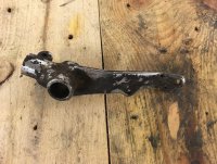
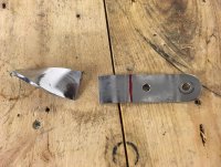
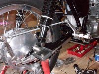
Then I looked at the stock set up again - see attached. This set up is also a 'direct link' to the foot. The pedal goes to the pivot shaft and then there is a flange up to the point where the brake rod connects. In the case of connecting a brake rod directly to the rear set pedal, the only difference would be a slightly more offset rotation point for the pivoting of the brake rod in the pedal itself (swing arm movement), plus as SONIC mentioned, the tendency for the rod to want to 'straighten' itself under heavy loads. To combat this, an extra stiff rod could be used. But I have the feeling a M6 threaded rod with a matching aluminium tube/sleeve, together, will form a decently strong connection. The actual offset that needs to be bent up doesn't seem all that bad either.
I think I'll try this method and If I hate the feedback or the movement in the pedal from swingarm movement, I'll go the cable route but make up something myself from an SR250 clutch cable and SR250 clutch cable bracket - it even already has the cable clevis!
Note that with the pull to the bottom, if anything should happen to your stay rod, the drum will rotate pulling the rear brake into full lock. Not fun at 65 mph on Folly Beach road!
True, but as mentioned above, the SR does not have a stay like most other bikes. Besides, there will be a mechanical stop for the pedal as well . to hold against the spring pressure which returns the brake arm.
True, but as mentioned above, the SR does not have a stay like most other bikes. Besides, there will be a mechanical stop for the pedal as well . to hold against the spring pressure which returns the brake arm.
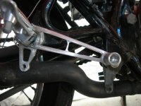
That looks about right right there!
I think a small bend to get around the frame there should be fine. You could also turn up an oversize stud and bolt one end to the inside of the pivot and the other to the brake rod to offset around the tube. Not sure which would be a better choice honestly.
Those linkage angles are terrible, the arms should be more or less parallel. Pic is my 360 before bending up a link rod
As 'We' had a 1960's BSA C15 250 pulling 115 mph around 1974. A 100 mph OHC motor should be easiy? Factory modified C15 only made 17bhp but at the time there were tuning parts from America available (1989 XR200 could be made to put out 22bhp, 24 bhp with Wiseco 'kit but then didn't last very long)
True. The angles will be adjusted for optimum mechanical work. This was just a mock up. Thanks for the pic, looks like a good set up - a bit like my first idea/intention!
crazypj said:
As 'We' had a 1960's BSA C15 250 pulling 115 mph around 1974. A 100 mph OHC motor should be easy?
This site uses cookies to help personalise content, tailor your experience and to keep you logged in if you register.
By continuing to use this site, you are consenting to our use of cookies.