cx'y 500

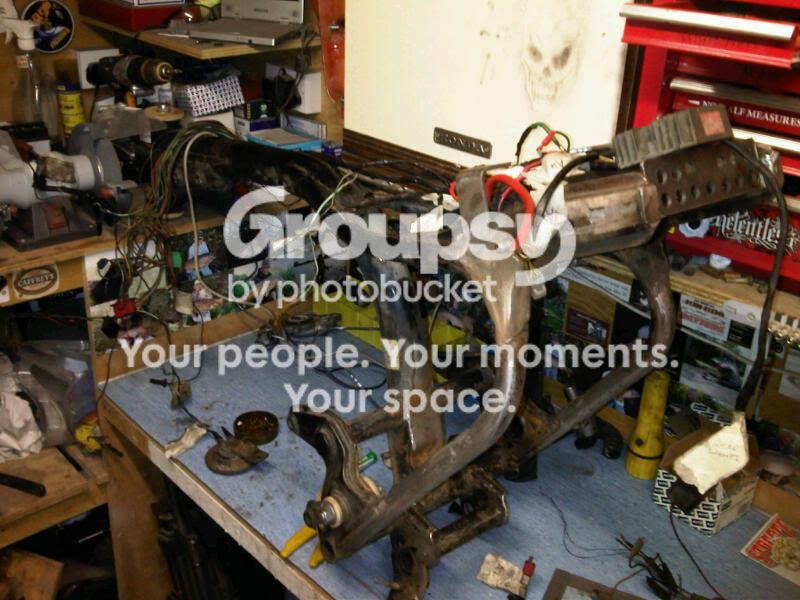
Only problem with shifting stuff around is the wires are to short, or to long.
My starter solonoid was right beside the battery on the original bike and now the live from the battery is to short.
IMG00871-20110817-1104.jpg

I nipped into town and grabbed a few bits to tidy up things a bit, while I was there I saw this really cool old Nimbis combination
IMG00881-20110817-1311.jpg

The tappets are on show and you can see the valve springs
IMG00882-20110817-1312.jpg

Now that is something I would like to play with [:p]
Anyway I grabbed a new live lead and soldered new ends on it once it was cut to length
IMG00873-20110817-1112.jpg

IMG00876-20110817-1125.jpg

Its really chunky wire and my electric soldering iron just isnt up to the job so I dug out some of my plumbing solder and flux
IMG00877-20110817-1128.jpg

Now on the drawing, off the battery I have a solid red and a red/yellow plus the main live, while this is right on my bike the red and a red/yellow plus the main live are on the solonoid side, its the same thing really.
IMG00878-20110817-1213.jpg

I made my new set up same as the old one, but I changed the 20amp glass fuse for a blade type. and as the red/yellow goes straight to the regulator rec I cut it shorter and will run it straight to it.
IMG00879-20110817-1233.jpg

I need an earth for the battery, so I drilled and tapped out the frame for a flat head hex bolt.
IMG00885-20110817-1444.jpg

Spot welded it to hold it in place
IMG00887-20110817-1631.jpg

then on the other side put a penny washer and a couple of nuts. after the powdercoat is done I'll cut round the washer to leave a good ground for the earth.
IMG00886-20110817-1631.jpg

I'm going to run the starter wire from the solonoid to the starter motor through the frame so I drilled and filed a couple of holes
IMG00884-20110817-1347.jpg

On the face of it there doesnt look like much to cover my time today, but the liitle things are usually what eat up time.
 
I havent either mate, I think its german as on the bars was a copper plate with the name of the bike and some german stuff.

I would love something like that mate.
 
When I striped the bike down I labeled up the loom. Tonight I thought I would see if I could make some sense of it.
IMG00889-20110817-2033.jpg

I draped the loom over the bike withe the marker for rear lights at the rear of the frame then cross referenced the loom with the drawing
IMG00890-20110817-2034.jpg

Working my way forward I untaped the loom looking for any dodgy wires and connections and repairing them as I went.
IMG00891-20110817-2037.jpg

The rear of the loom is looking good and all taped back up again.
I taped half way to the front of the bike, then stopped and taped from the front to back and covered the joint with red tape. If there is a problem at a later date I can remove the red tape and unwrap forwards or to the rear of the bike.
IMG00892-20110817-2115.jpg

Its not looking to bad at the moment and I think I should be able to make it all work. One step at a time and I'll work my way right through the job, no worries.
IMG00894-20110817-2117.jpg

Tomorrow is another day [:D]
 
Thats really cool mate, thanks.

I've never seen one before, but I would love that bobber.
 
Right then,
Heres a question; I want to keep the area under the seat, behind the engine as clear as possible so I want to run the thick black lead from my starter solonoide (under the seat) to my starter motor through my frame. The longest lead I can find in my local auto spares shop is 60cm long but I need a bit 70cm long.
The guy in the shop says to buy a set of jump leads and just cut the black lead to the length required as its the same stuff.
Is that true?
Or is the guy just trying the hard sell?
 
All you really need is a wire of the correct gauge with appropriate insulation for an exterior application.

At first glance, his suggestion seems sound, as jumper cables are of appropriate gauge and insulation type.

You will need to crimp/solder a new end on it like you did for the lead from the battery to the relay, but you know how to do that just fine.

Your local electrician supply company will have appropriate wire as well, but it could be much more expensive that cutting up a cheap pair of jumpers.

Improvisation always makes for better stories, if equivalent results are achieved!
 
The one thing i will say about buying the appropriate wire is you don't have to worry about knicking the cable open so easily, unlike when you are trying to spserate jumper cables. Honestly i can't imagine the wire by itself would be more expensive than jumper cables.
 
My mate sideshowbob sent me a link to an automotive wiring site an its only £3.75 a meter so thats the way I'm going to go, but thanks loads for the input lads.

In other news today;

Inside the rear engin case there is an oil seal between the water pump and the internal oily bits. I noticed when I removed the generator that the oil seal has perrished and got scale build up
IMG00898-20110818-1733.jpg

Lookin a bit grim
IMG00899-20110818-1733.jpg

I levered it out and it fell apart in my hand
IMG00900-20110818-1734.jpg

There was quite a bit of it left in the seat as well
IMG00901-20110818-1734.jpg

I gave it a clean out and checked around the outside of the case. It looks like because the seal had failed it was leaking water into the oil, and thats why it was a bit gloopy when I drained it. The other thing I noticed was there was obviously some cooland coming out of the drain hole because the seal had failed, and the previous owner thought the best cure was to plug the hole with a screw.
IMG00902-20110818-1741.jpg

I removed the screw and the drain hole was jammed with dirt.
I was able to get a small drill bit in there with a pair of point nose pliers and get most of the dirt out
IMG00904-20110818-1747.jpg

Then I went in from the other side with a sharp pick
IMG00906-20110818-1803.jpg

I managed to clear it through and blast a bit of air through it with my compressor
IMG00907-20110818-1806.jpg

Now I just need to order an oil seal from David Silver Honda and it should work as it was supposed to when it rolled of the production line. If you own a CX500 - 650 or custom and you have coolant weeping out the drain hole there is a good chance the oil seal has gone, so dont just plug up the hole, change the seal.

N.B. I was thinking about this small fault last night and when buying a CX it has to be one of the things to look for when you are looking over the bike. It could be a cotly repair as the engine will need to come out as if the small drain hole has been blocked then the oil seal has gone.
Or, if you are happy to do the work yourself, then it has to be a good bargaining chip to get the price right down.
 
IED said:
I'm going to run the starter wire from the solonoid to the starter motor through the frame so I drilled and filed a couple of holes

coming along nicely. You might want to look into some grommets around those holes for your live cable. You don't want that shorting out due to vibration/wear.

There's something therapeutic about wiring. Just taking your time and working through the different systems. I may be a little weird, but I enjoy it.

cheers
ian
 
A while back I ground in my valves and changed 4 valve adjuster screws, I didnt check the valve clearences at the time, but I'm scratching round for things to do so I'm gonna do them now.
First off I cant do it totally as the Haynes manuel describes because I have the rear engine cover off and cant line up the marks on the fly wheel with the engine case.
So, heres how I went about it.
I need the piston on the right to be at top dead center "TDC" all the valves are in the closed position.
To do this I removed both spark plugs, then rotated the fly wheel to a point where the exhaust valves opened then closed. This is the end of the cycle. The piston should be at the top of the cylinder, and to confirm this I placed a screw driver in the spark plug hole
001-1.jpg

I removed the screwdriver then rotated the flywheel anti-clockwise.
The inlet valves then opened and closed. You can see from the photo the push rod at the top is up, pushing the rocker and valve down, and the valve is open. If the engine was running it would be sucking in fule from the carbs
005-1.jpg

As it does this the piston is on its way down and the valves shut, as indicated with the screwdriver
006-1.jpg

Then it comes back up it compresses the fuel mixture and when the piston reaches the top of the cylinder (T.D.C.) the spark plug will spark and ignite the fuel mixture forcing the piston down. but T.D.C is where we want it to be. At this point all the valves should be shut. Rock the flywheel gently back and forth and you will see minute movements up and down of the screwdriver. When you can judge it to be half way between up and down and for a very brief moment the screw driver does'nt move you will be at T.D.C.
007-1.jpg

I checked for signs of movement in the rockers, but there was none.
008-1.jpg

Now we can loosen off the locking nuts on the inlet valve adjusting screws and set the gap to 0.010mm. If you are going to have a go at this check you biks manuel for gap sizes.
009.jpg

Once you tighten up your locking nuts, re check the gap. It should bu a snug fit not to tight with just a small amount of friction when you move the feeler guage.
Do both inlet as they are on the same rocker, then do the exhaust without moving the engine flywheel. My exhaust gap is 0.012mm so I had to use two feelers. This brings me to an important point, some of the feelers are thinner than paper so be very carefull you dont have extra feelers stuck together you dont know about, that will give you the wrong gap. Its worth checking.
010-1.jpg

So once you have done the exhaust valves, follow the methods above to do the left side
011.jpg

Once you've done that side give your self a pat on the back, because it wasnt as hard as you thought it would be
2011-02-0623.jpg
 
bikeboy said:
coming along nicely. You might want to look into some grommets around those holes for your live cable. You don't want that shorting out due to vibration/wear.

There's something therapeutic about wiring. Just taking your time and working through the different systems. I may be a little weird, but I enjoy it.

cheers
ian

I do to mate, it occupies my mind and stops me getting bored.
 
Been busy today.
Phoned David Silver Honda this morning and got an electrex world stator generator, and water pump oil seal on order, so they should be here in a day or two, then I can get the motor back together.
Then jumped in the car and shot off to Colchester to drop my frame into Impact coatings.
IMG00934-20110822-1301.jpg

Really nice people and the quoted me £80.00 to blast and powdercoat the frame, frame engine mount and swing arm.
IMG00936-20110822-1302.jpg

Wasn't alowed to go any further than this, but they tell me in 7 to 10 days I should be getting a call.
IMG00937-20110822-1302.jpg

I should have plenty to do untill then if my other bits arrive fairly soon.
 
Today my Cam shaft oil seal and my Electrex world stator generator arrived, so I didnt waste any time fitting them.
IMG00944-20110823-1514.jpg

Oil seal was a doddle to fit and only took a couple of minutes
Then decided to fit the stator generator. Its made by a company called Electrex world, Griff and Fighter MC put me onto the company when the rec/reg kept blowing on my blade. they make patten parts but better than original.
IMG00943-20110823-1513.jpg

Heres the weard thing though, direct from electrex world the generator is £95.00 + V.A.T. And from David Silver Honda its £79.00 + the vat. Not to sure how that works, but I'm glad I checked with DSH before going direct.
Anyway, you need to use your old pickups so I cut them out of the old generator loom and threaded the wires along with the new wires through the collector block that clamps between the engin case and the cover
IMG00945-20110823-1529.jpg

Then threaded the wires through the rear engine case and bolted in the pickups
IMG00946-20110823-1533.jpg

Generator went in next
IMG00947-20110823-1548.jpg

They supplied new cap head bolts.
I fitted the new gasket,
IMG00948-20110823-1549.jpg

Then the stator cover I refinished a couple of weeks back
IMG00949-20110823-1553.jpg

Thats about it for now on the electrics, as I dont want to make the ends of the wires off untill I get my frame back and can guage the lengths better.
IMG00950-20110823-1604.jpg

I made sure all the mating surfaces were clean, then placed the gasket over the engine. Then put then placed the case on the dowels and just started all the bolts through the gasket holes to make sure it all lined up.
IMG00952-20110823-1623.jpg

Then tightened it down to the corect torque
IMG00954-20110823-1643.jpg

Water pump went on next with the refurbished water pipe to the rad
IMG00956-20110823-1652.jpg

Then the carbs, starter motor and crank case breather went on
IMG00967-20110823-1907.jpg

And the engin is back together, and ready for the frame to be bolted over it.
IMG00966-20110823-1759.jpg

The hours spent on the little fiddley bits were worth while and I'm pleased with the overall look of the motor.
 
That thing looks great! I like the crank case breathers. Did you put a new mechanical seal behind the water pump impeller? I'll be glad when I can work on my engine.I look for your post every day to see what you got done.Nice job.
 
The front break callipers like everything else on this bike needed looking at, so some time back I took them apart, then cleaned them up a bit ready for re-finishing.
I orded up a set of new seals and when they arrived got stuck into doing them up.
First thing I had to do was clean out the gunge from the groove where the seal sits
IMG00969-20110824-1458.jpg

Easy little job with one of these hobby tools. Mine is made by Silverline and only cost about 20 quid.
dremel.jpg

Done in seconds.
IMG00970-20110824-1459.jpg

Next I masked up everything I didnt want paint on
IMG00972-20110824-1502.jpg

Then gave it a shot of acid etch primer. This stuff is horrible, and I've poisened myself a couple of times with it so be carefull and wear breathing AND eye protection, as a painter friend of mine tells me it can be absorbed through the eyes and poisen you that way.
IMG00973-20110824-1517.jpg

Two of them, then two of the top stuff. I used engine enamel as its heat resistant, and is about 1/3 of the cost of calliper paint. Just remember to wash down the calipers when youre bleeding them.
IMG00975-20110824-1517.jpg

I left mine to cure for 3 or 4 days before handling them.
 
So the bodys are painted and the other parts cleaned, they are ready to go back together.
IMG00983-20110825-1910.jpg

The oil seal is the first thing to go back is, and needs a good coat of break fluid to lube it and seat it in the groove.
IMG00984-20110825-1915.jpg

Same goes for the piston. Dont use anything but break fluid to lube these parts or you might contaminate your fluid when you bleed the breaks through.
IMG00987-20110825-1916.jpg

Should be a nice snug push fit.
IMG00988-20110825-1918.jpg

Next fit the dust seal and hold it in place with the circle clip.
IMG00989-20110825-1919.jpg

Then the bleed nipple went in
IMG00992-20110825-1921.jpg

The other half of the calliper has two pins that locate into two holes, a little copper slip will help them to move inside the holes
IMG00996-20110825-1925.jpg

Next I changed the old bolts for same size thread, stainless cap head bolts. I think they look good against the gloss black
IMG00997-20110825-1930.jpg

Once they were both done I went over them with a water soaked rag just to remove any break fluid that may have got on to the paint.
IMG00998-20110825-1952.jpg

I'll wait until I have them back on before I fit the new pads.
Another job done and another box ticked. I think I might have a go at polishing the top yoke tomorrow.
 
Mini update on the pegs
I cut the original pegs up from my fireblade and welded them to the back plates of the CX.
IMG00847-20110815-1738-1.jpg

They are now painted
IMG00978-20110825-1858.jpg

And back together and ready to fit when the frame gets back from powdercoat.
IMG00982-20110825-1906.jpg

The box of bits to do up is getting smaller every day. [:D]
 
I brought this today, Its a Ducati 748 electric fan.
IMG01000-20110826-1144.jpg

If you remember a while back I removed the temp sender unit from the thermostat housing and replaced it with a thermal switch.
IMG00774-20110803-1800-1.jpg

I removed the fan to give the housing a good clean and measure up for brackets to fix it to the CX cowling.
IMG01004-20110826-1159-1.jpg

To get it as near to center as I could I needed my fixing brackets to be 35mm
IMG01002-20110826-1153-1.jpg

They were simple enough to do, as I just cut down a couple of angle brackets I had laying round. I drilled the CX cowel and bolted it into place
IMG01008-20110826-1312-1.jpg

I like the look of the CX cowling so I wanted to keep it, and any changes I make wont be that obvious because it will all be hidden inside it.
IMG01009-20110826-1313-1.jpg

So now it just needs paint to bring it in with the existing set up.
IMG01011-20110826-1323-1.jpg

Next I'm gonna be extending the leads on the fan its self.
 
Back
Top Bottom