
You are using an out of date browser. It may not display this or other websites correctly.
You should upgrade or use an alternative browser.
You should upgrade or use an alternative browser.
Father Son 75 CB200T Rise From the Ruins
- Thread starter Texasstar
- Start date


That's a lot of missing metal. It'd be tempted to either box in the frame at that point or perhaps replace that main spine with a duplex tube arrangement from just above the swingarm pivot to below the tank. Use Chrome moly 4130 tube from onlinemetals.com or Aircraft Spruce or your local supplier.

Texasstar
Can't is a four letter dirty word
will doteazer said:That's a lot of missing metal. It'd be tempted to either box in the frame at that point or perhaps replace that main spine with a duplex tube arrangement from just above the swingarm pivot to below the tank. Use Chrome moly 4130 tube from onlinemetals.com or Aircraft Spruce or your local supplier.
Texasstar
Can't is a four letter dirty word
Cb200 head exhaust ported. Raised roof on exhaust ports. Started with a pencil carbide tip dremel bit. Then used an 80 grit small drum roller. Hand sanded with 320 grit. Couldn't find a small 240 grit drum roller... Guess we could have glued some 220 to a used small drum roller...
Attachments


Texasstar
Can't is a four letter dirty word
We have found three places to mount the fairing to... We need room to tuck our long legs inside the fairing..do we need bracing to the front of the fairing like the pic since our fairing is one piece (The small round bar is for mock up.) maybe use a piece of PVC to brace to the front so there are no fairing bolts on the front of the fairing.
We were going to take thin wall mild steel and weld tabs to attach just beneath where the front rod is in front of the tank.
The air intake on the fairing has another good place to attach a tab to the frame both top and bottom.
Then another mild steel tube below the engine.
We were going to take thin wall mild steel and weld tabs to attach just beneath where the front rod is in front of the tank.
The air intake on the fairing has another good place to attach a tab to the frame both top and bottom.
Then another mild steel tube below the engine.
Attachments


Texasstar
Can't is a four letter dirty word
Working on the combustion chamber porting. Rounding off the sharp edge leading to the valve. Should we leave it to keep the compression ratio at the expense of flame propagation and flow?
Should we remove the small triangle at the base of the plug?
Should we remove the small triangle at the base of the plug?
Attachments


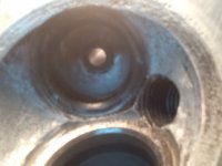

Those ridges are likely to be causing some shrouding. Not a bad idea to round them off a bit, but don't go crazy. They may actually be helping to out a bit if you decide to switch out to a higher duration cam in the future.
If you have more than one head to work with, then by all means grind 'em down and see what happens.
If you have more than one head to work with, then by all means grind 'em down and see what happens.
For the fairing mounts, I use one on the steeringhead pointing straight forward. That Seeley has a straight tube with a flat bar across the end for double bolts. That's overkill. Get some RS125 fairing mounts and screws and then source steel tube that the RS125 mount will slide into.
You can see the side and front mount on this RS250R
 . All QD
At the rear on a CB175/160 I use flat 1" x 1/8" aluminum strap and Dzus fastener on each side of the motor or a GSXR isolastic mount. On other bikes I'll fabricate a tubular bracket that reaches each side of the fairing and use similar RS125 slip in nylon mounts. That straight tube can be made to attach to the motor or frame.

On some bikes, I have fabricated a 3" length of thin wall tube with a 4" strip of 1" x 1/8" steel welded across the top. That slips over the cross tube and is glassed onto the inner surface of the fairing for an invisible mount.
Whichever way I mount them, the idea is that the nylon slides inside the cross or front tubes and is drilled through to take an R pin. To get the fairing off is pull the pin, wriggle the end caps off and remove the fairing. On and off in seconds.
On a conventional race fairing with long thin breakable ears, I usually fabricate a light bracket on the steering head or into the center of the steering head tube and fasten the fairing to that with one screw or Dzus faster at each side.
TZ Yamahas used a bracket that bolted to two small mounts on the frame.

You can see the large dome head screws on the side and front of these TZs and the screen side mount

Both TZs were sold years ago and that RS250 was finished and returned to the owner fully rebuilt and ready to race sniff, sniff... Onwards and upwards. Next project please...
You can see the side and front mount on this RS250R
At the rear on a CB175/160 I use flat 1" x 1/8" aluminum strap and Dzus fastener on each side of the motor or a GSXR isolastic mount. On other bikes I'll fabricate a tubular bracket that reaches each side of the fairing and use similar RS125 slip in nylon mounts. That straight tube can be made to attach to the motor or frame.
On some bikes, I have fabricated a 3" length of thin wall tube with a 4" strip of 1" x 1/8" steel welded across the top. That slips over the cross tube and is glassed onto the inner surface of the fairing for an invisible mount.
Whichever way I mount them, the idea is that the nylon slides inside the cross or front tubes and is drilled through to take an R pin. To get the fairing off is pull the pin, wriggle the end caps off and remove the fairing. On and off in seconds.
On a conventional race fairing with long thin breakable ears, I usually fabricate a light bracket on the steering head or into the center of the steering head tube and fasten the fairing to that with one screw or Dzus faster at each side.
TZ Yamahas used a bracket that bolted to two small mounts on the frame.
You can see the large dome head screws on the side and front of these TZs and the screen side mount
Both TZs were sold years ago and that RS250 was finished and returned to the owner fully rebuilt and ready to race sniff, sniff... Onwards and upwards. Next project please...
Ports:
Make the valve guide boss much thinner. It's a big fat lump that hinders flow and it's in the high pressure high flow part of the port. Leave that triangle and leave the recess around the valve seats - except where it meets the bore, radius that slightly and just break the edges. When the valve seats are cut on a Serdi, they will look much nicer.
Make the valve guide boss much thinner. It's a big fat lump that hinders flow and it's in the high pressure high flow part of the port. Leave that triangle and leave the recess around the valve seats - except where it meets the bore, radius that slightly and just break the edges. When the valve seats are cut on a Serdi, they will look much nicer.
Texasstar
Can't is a four letter dirty word
thanks Teazer! Looking forward to your next project...Maybe a LSR project???teazer said:Ports:
Make the valve guide boss much thinner. It's a big fat lump that hinders flow and it's in the high pressure high flow part of the port. Leave that triangle and leave the recess around the valve seats - except where it meets the bore, radius that slightly and just break the edges. When the valve seats are cut on a Serdi, they will look much nicer.
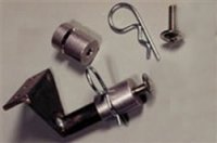
somebody needs to beat that can am 125 record...we think you could do it 140+We ordered airtechs fairing quick releases before knowing about the rs125 but they are similar. Yours look lighter...sigh Home work is finished...out to the shed.
Attachments
Texasstar
Can't is a four letter dirty word
thanks Sonreir and ...the devcon f is next...Sonreir said:Those ridges are likely to be causing some shrouding. Not a bad idea to round them off a bit, but don't go crazy. They may actually be helping to out a bit if you decide to switch out to a higher duration cam in the future.
If you have more than one head to work with, then by all means grind 'em down and see what happens.
Attachments


Texasstar
Can't is a four letter dirty word
left side valve guide stocky rights side after working out...We are getting closer to Serditeazer said:Ports:
Make the valve guide boss much thinner. It's a big fat lump that hinders flow and it's in the high pressure high flow part of the port. Leave that triangle and leave the recess around the valve seats - except where it meets the bore, radius that slightly and just break the edges. When the valve seats are cut on a Serdi, they will look much nicer.
Attachments


Texasstar
Can't is a four letter dirty word
We changed the riding position by flipping Perreault's clip on and have a short turn throttle and shorty brake and clutch leavers coming from Les at Vintage Advantage. We need to install a safety tether switch also and a NHS steering stabilizer on the way is on the way from Fast From The Past.
Attachments

wynand2000
Active Member
Hi Father & Son!
You guys can be really proud of what you`re achieving here....man what a ride it`s becoming
The working together and the fun you guys spread in the video`s (at least in the few ones I`ve seen) is a lesson for the world, and even Mom was smiling in a video concerning motorcycles.
Will follow from now on!
Continue having a great time.
You guys can be really proud of what you`re achieving here....man what a ride it`s becoming
The working together and the fun you guys spread in the video`s (at least in the few ones I`ve seen) is a lesson for the world, and even Mom was smiling in a video concerning motorcycles.
Will follow from now on!
Continue having a great time.
Texasstar
Can't is a four letter dirty word
thanks wynand2000 we will!wynand2000 said:Hi Father & Son!
You guys can be really proud of what you`re achieving here....man what a ride it`s becoming
The working together and the fun you guys spread in the video`s (at least in the few ones I`ve seen) is a lesson for the world, and even Mom was smiling in a video concerning motorcycles.
Will follow from now on!
Continue having a great time.
Port is getting there. Now measure the port shape of pour molding rubber in and see if it has the basic taper-straight-expansion shape in that picture. Critical Diameter is roughly at the guide and it should expand through the valve area.
You still have room to grind metal out either side of that guide if you need to. Focus on shape and relative sizes of the sections so they all work together.
On a high speed motor, you can also shorten the guide significantly and undercut the stem a little.
You still have room to grind metal out either side of that guide if you need to. Focus on shape and relative sizes of the sections so they all work together.
On a high speed motor, you can also shorten the guide significantly and undercut the stem a little.
Texasstar
Can't is a four letter dirty word
The diameter at the exhaust valve seat is 19.8mm and the width across at the guide boss is 25mm but is a squished oval 18mm floor to ceilling and it expands to 29 mm at the end of the exhaust port. Open up the valve bowl seat to 22-23mm??? The plans are to go to 29mm intake and keep the 24 exhaust in the future.. To be in the correct ratio. Do we want to keep the velocity up at the valve seat area or create a Venturi at the valve guide to prevent reversion?teazer said:Port is getting there. Now measure the port shape of pour molding rubber in and see if it has the basic taper-straight-expansion shape in that picture. Critical Diameter is roughly at the guide and it should expand through the valve area.
You still have room to grind metal out either side of that guide if you need to. Focus on shape and relative sizes of the sections so they all work together.
On a high speed motor, you can also shorten the guide significantly and undercut the stem a little.
Attachments

Yes.
It's not so much about reversion it's about how a pipe and orifice flow. Straight pipes are good to straighten out flow but they slow things down. The decreases in area at the inlet end increases gas velocity, but what's important there is CD area and gas velocity at that point. Larger or smaller port areas either side of that are not the issue. Smaller than required chokes the port. Larger than it should be at any point leads to loss of velocity and increased turbulence.
Work out gas velocity at each part of the port on a spreadsheet and also work out the optimum port shape working from the valve back and compare the two sets of answers. That will tell you where to add or remove metal in the intake port. Vizard or Bell spell out the shapes and relative size ranges. Construct a spreadsheet using those values in each column and populate the sheet with a range of valve sizes and from that you can calculate mean gas velocity at each point, but really the only two that matter are at the CD and carb.
It's not so much about reversion it's about how a pipe and orifice flow. Straight pipes are good to straighten out flow but they slow things down. The decreases in area at the inlet end increases gas velocity, but what's important there is CD area and gas velocity at that point. Larger or smaller port areas either side of that are not the issue. Smaller than required chokes the port. Larger than it should be at any point leads to loss of velocity and increased turbulence.
Work out gas velocity at each part of the port on a spreadsheet and also work out the optimum port shape working from the valve back and compare the two sets of answers. That will tell you where to add or remove metal in the intake port. Vizard or Bell spell out the shapes and relative size ranges. Construct a spreadsheet using those values in each column and populate the sheet with a range of valve sizes and from that you can calculate mean gas velocity at each point, but really the only two that matter are at the CD and carb.