
You are using an out of date browser. It may not display this or other websites correctly.
You should upgrade or use an alternative browser.
You should upgrade or use an alternative browser.
Texas Two Step Taco
- Thread starter Texasstar
- Start date

John Murray
Been Around the Block
I bet you have a dyno in your garage also...
Sent from my iPhone using Tapatalk
Yes I do, it's homemade and kinda primitive but it does the job. Having a dyno on hand speeds up the development process by a factor of about 10 I reckon.. best thing I ever did.

Texasstar
Can't is a four letter dirty word
Or we could call it the (name your least favorite politician or rich person) tune.
True
Sent from my iPhone using Tapatalk
Texasstar
Can't is a four letter dirty word
I have been thinking about waves and all the expansion chambers hanging from BB’s ceiling. How they have different angles. He said the majority of theoretically “right” chambers have been practically wrong.
With every section I made I was wondering where the pulse traveled. Does it travel like an ocean wave when reflected? Wouldn’t the pulses reflect differently off of the different angles?
Sent from my iPhone using Tapatalk
With every section I made I was wondering where the pulse traveled. Does it travel like an ocean wave when reflected? Wouldn’t the pulses reflect differently off of the different angles?
Sent from my iPhone using Tapatalk
Texasstar
Can't is a four letter dirty word
Or we could call it the (name your least favorite politician or rich person) tune.
I quote you all the time about our cb175 “that it flaps more than a politicians lips”
Sent from my iPhone using Tapatalk

Was that me? Seems I don't hold politicians in high regard.
On the cone question:
The larger the cone angle, the stronger the pulse is. Until it's too big and the waves are disrupted.
Think of a straight parallel wall pipe and the opening at the end as two extremes along the range of that variable. In a straight pipe, teh wave just travels along and no much happens to it. There's some friction along the walls but not much else. When a pulse (wave) hits the open end, there is a sudden expansion into what is basically infinite space. That cause the wave to be reflected back but as a negative pressure wave. A sudden opening like that works beast at only one RPM or multiples thereof. At all others, it's not so good.
Now think of a divergent nozzle (the first stages of your pipe) as a series of small stepped open ends. Now we have a long pulse being generated as the first wave travels down the pipe. Now add a second stage and what that does is to add a stronger reflected wave at a later time, so it arrives later. There's all sort of math involved but basically you now have two waves arriving at different times with different intensity.
So for example you might design the pipe so that the first stage helps evacuate the cylinder as the exhaust port starts to operate. You might want that second stage wave to arrive after blowdown to "suck" gas all the way from the crankcase through the transfer ports to aid scavenging.
At some point that new fresh mixture is flowing out of the transfers, around the combustion chamber and straight out the exhaust pipes, so we want to push some of it back in to sort of supercharge the cylinder. That's where the convergent nozzles aka baffle cones come in.
With a pipe closed at one end (opposite of the example above) a wave is reflected with the same sign. A positive wave will be reflected back as a positive wave and in an expansion chamber it's often called a stuffing wave. The idea is that when the exhaust pule gets all the way down to the baffle cones the effect is like the expansion part but in reverse. Think of it as a series of closed ends reflecting back a positive wave which will "push" mixture back into the cylinder.
The belly section is just there to adjust the length and therefore the time at which those pulses arrive and the angles change the magnitude of the waves within certain limits. For example subtle waves have less peak effect but tens also to have less adverse effects off peak so they are well suited to a mild tune street bike. Big fat pipes are great on bikes with a cylinder wall full of holes and big transfer ports and large crankcase volumes, but are less suitable on motors with few/small ports and small crankcase volume to draw from. That's why huge fat pipes work on modern motors but are not so good on our old clunkers. Back in the day crankcase volumes were small to create higher primary compression to push gas through the transfers, but that creates a really narrow powerband because the short push pulse from the bottom end had limited time to work and was strongest high revs.
That's somewhat oversimplified and you have to keep in mind that I'm no expert. There are people who really understand this stuff at both a theoretical and empirical level. I just do this for fun and try to keep learning.
One other thing I learned but tend to forget when I'm welding a pipe is that it's best to weld along the seam of each cone and then planish them or roll them to get the seam smooth and the cone circular. Next thing is to repeat that after welding each section to smooth out distortion and steps at each join. I'm not a great welder so when a weld is going well, I keep going and then see how badly it distorted after I finish the whole pipe - not ideal. Get the cones/steps/segments aligned and weld and smooth the step out before going to the next segment.

Remember that this information is worth every penny you pay for it....

On the cone question:
The larger the cone angle, the stronger the pulse is. Until it's too big and the waves are disrupted.
Think of a straight parallel wall pipe and the opening at the end as two extremes along the range of that variable. In a straight pipe, teh wave just travels along and no much happens to it. There's some friction along the walls but not much else. When a pulse (wave) hits the open end, there is a sudden expansion into what is basically infinite space. That cause the wave to be reflected back but as a negative pressure wave. A sudden opening like that works beast at only one RPM or multiples thereof. At all others, it's not so good.
Now think of a divergent nozzle (the first stages of your pipe) as a series of small stepped open ends. Now we have a long pulse being generated as the first wave travels down the pipe. Now add a second stage and what that does is to add a stronger reflected wave at a later time, so it arrives later. There's all sort of math involved but basically you now have two waves arriving at different times with different intensity.
So for example you might design the pipe so that the first stage helps evacuate the cylinder as the exhaust port starts to operate. You might want that second stage wave to arrive after blowdown to "suck" gas all the way from the crankcase through the transfer ports to aid scavenging.
At some point that new fresh mixture is flowing out of the transfers, around the combustion chamber and straight out the exhaust pipes, so we want to push some of it back in to sort of supercharge the cylinder. That's where the convergent nozzles aka baffle cones come in.
With a pipe closed at one end (opposite of the example above) a wave is reflected with the same sign. A positive wave will be reflected back as a positive wave and in an expansion chamber it's often called a stuffing wave. The idea is that when the exhaust pule gets all the way down to the baffle cones the effect is like the expansion part but in reverse. Think of it as a series of closed ends reflecting back a positive wave which will "push" mixture back into the cylinder.
The belly section is just there to adjust the length and therefore the time at which those pulses arrive and the angles change the magnitude of the waves within certain limits. For example subtle waves have less peak effect but tens also to have less adverse effects off peak so they are well suited to a mild tune street bike. Big fat pipes are great on bikes with a cylinder wall full of holes and big transfer ports and large crankcase volumes, but are less suitable on motors with few/small ports and small crankcase volume to draw from. That's why huge fat pipes work on modern motors but are not so good on our old clunkers. Back in the day crankcase volumes were small to create higher primary compression to push gas through the transfers, but that creates a really narrow powerband because the short push pulse from the bottom end had limited time to work and was strongest high revs.
That's somewhat oversimplified and you have to keep in mind that I'm no expert. There are people who really understand this stuff at both a theoretical and empirical level. I just do this for fun and try to keep learning.
One other thing I learned but tend to forget when I'm welding a pipe is that it's best to weld along the seam of each cone and then planish them or roll them to get the seam smooth and the cone circular. Next thing is to repeat that after welding each section to smooth out distortion and steps at each join. I'm not a great welder so when a weld is going well, I keep going and then see how badly it distorted after I finish the whole pipe - not ideal. Get the cones/steps/segments aligned and weld and smooth the step out before going to the next segment.
Remember that this information is worth every penny you pay for it....
John Murray
Been Around the Block
I've made a lot of pipes, and one thing I've always found useful is to allow some way of easily adjusting the length. I use EngMod2T to spec the pipe (though I really like Frits Overmars FOS simple system too) and it's always on the money. But, and it's a big but, all these design tools require some assumptions about exhaust temp that may not always be accurate, and it's not at all unusual to find that the length needs some small adjustment after testing. Come to think of it, just about every pipe I've made has had some adjustment after testing so I try to make this easy to do when I build it. Don't weld big permanent mounts on it until you're sure it's done, I sometimes use big hose clamps to attach the mounts until testing is finished. Another common thing to find is that as the engine is developed the EGT rises, again changing the pipes behaviour and possibly requiring adjustment.
Keep in mind that fluid flow and wave travel are different things - waves travel around pretty severe angles easily, but if you go too far they can be "smeared".
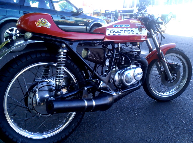
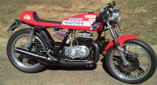
I'm not entirely sure the common belief that large volume chambers won't work with old style cylinders is true - I've used fairly big 5" belly pipes with tapered header and two stage diffuser on my Pursang engine with good results, and this is a simple single ex port with A & B transfers design. There's a photo, this bike was a lot of fun on the street.
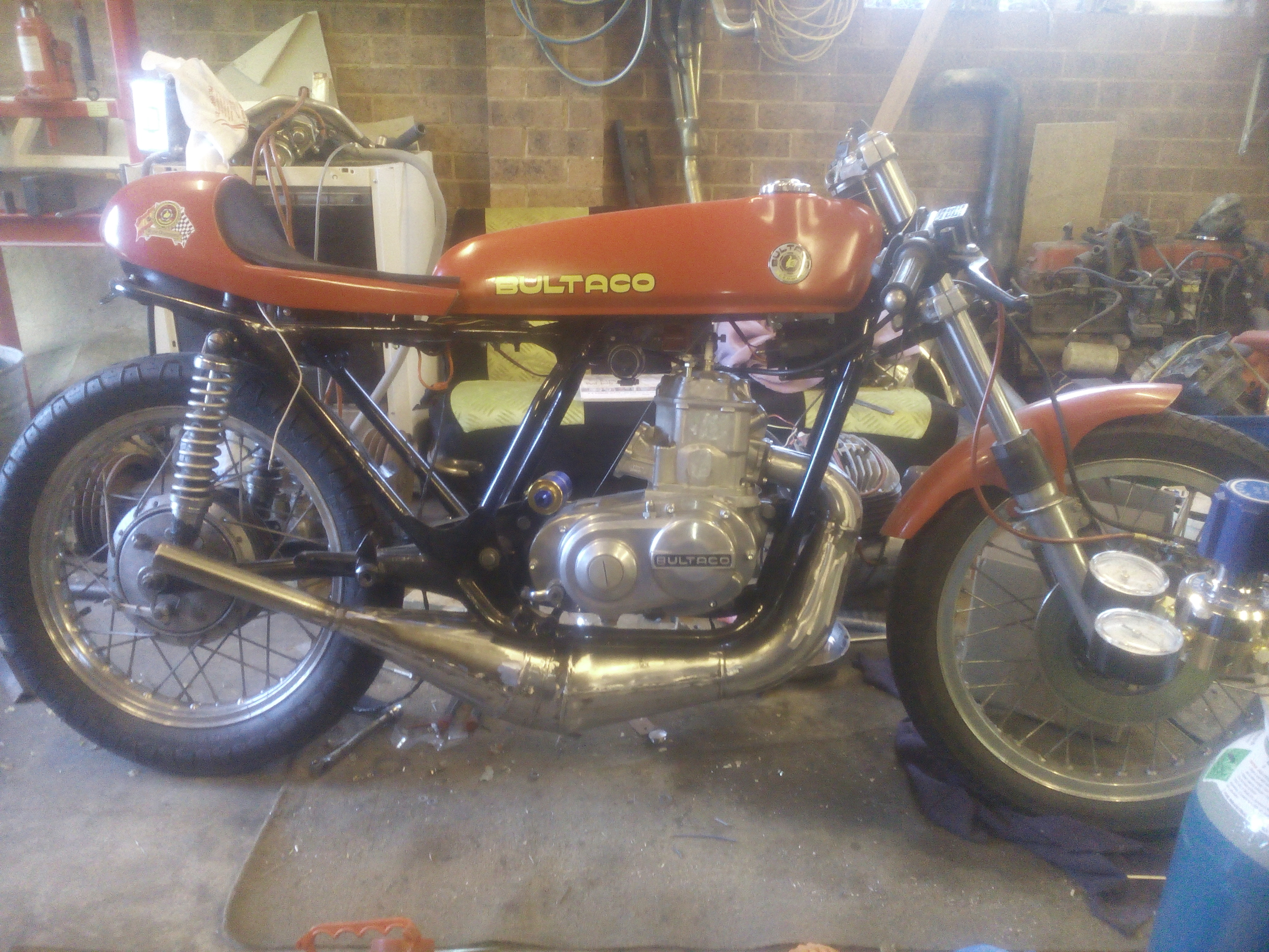
There's another photo of the bike with the water cooled engine and unpainted pipe and this one illustrates a very important point - if you take your photos out of focus even the roughest pipework comes out looking OK.
Keep in mind that fluid flow and wave travel are different things - waves travel around pretty severe angles easily, but if you go too far they can be "smeared".
I'm not entirely sure the common belief that large volume chambers won't work with old style cylinders is true - I've used fairly big 5" belly pipes with tapered header and two stage diffuser on my Pursang engine with good results, and this is a simple single ex port with A & B transfers design. There's a photo, this bike was a lot of fun on the street.
There's another photo of the bike with the water cooled engine and unpainted pipe and this one illustrates a very important point - if you take your photos out of focus even the roughest pipework comes out looking OK.
Texasstar
Can't is a four letter dirty word
I've made a lot of pipes, and one thing I've always found useful is to allow some way of easily adjusting the length. I use EngMod2T to spec the pipe (though I really like Frits Overmars FOS simple system too) and it's always on the money. But, and it's a big but, all these design tools require some assumptions about exhaust temp that may not always be accurate, and it's not at all unusual to find that the length needs some small adjustment after testing. Come to think of it, just about every pipe I've made has had some adjustment after testing so I try to make this easy to do when I build it. Don't weld big permanent mounts on it until you're sure it's done, I sometimes use big hose clamps to attach the mounts until testing is finished. Another common thing to find is that as the engine is developed the EGT rises, again changing the pipes behaviour and possibly requiring adjustment.
Keep in mind that fluid flow and wave travel are different things - waves travel around pretty severe angles easily, but if you go too far they can be "smeared".
I'm not entirely sure the common belief that large volume chambers won't work with old style cylinders is true - I've used fairly big 5" belly pipes with tapered header and two stage diffuser on my Pursang engine with good results, and this is a simple single ex port with A & B transfers design. There's a photo, this bike was a lot of fun on the street.
There's another photo of the bike with the water cooled engine and unpainted pipe and this one illustrates a very important point - if you take your photos out of focus even the roughest pipework comes out looking OK.
View attachment 224407
View attachment 224408
View attachment 224409
Is this the bike that was on the twostroke world string?
Sent from my iPhone using Tapatalk
Texasstar
Can't is a four letter dirty word
My question on the negative pressure wave is this? Does it bend? Like an ocean wave? Does the wave travel in unison along the complete circumference pipe and arrive at the destination at the same time or does the wave arrive at different time at different circumference of the pipe? The pipe has different distances based on the bends. Where does the reflection take place and how. Does the angle where the cone is attached to the prior piece matter in the reflection?Was that me? Seems I don't hold politicians in high regard.
On the cone question:
The larger the cone angle, the stronger the pulse is. Until it's too big and the waves are disrupted.
Think of a straight parallel wall pipe and the opening at the end as two extremes along the range of that variable. In a straight pipe, teh wave just travels along and no much happens to it. There's some friction along the walls but not much else. When a pulse (wave) hits the open end, there is a sudden expansion into what is basically infinite space. That cause the wave to be reflected back but as a negative pressure wave. A sudden opening like that works beast at only one RPM or multiples thereof. At all others, it's not so good.
Now think of a divergent nozzle (the first stages of your pipe) as a series of small stepped open ends. Now we have a long pulse being generated as the first wave travels down the pipe. Now add a second stage and what that does is to add a stronger reflected wave at a later time, so it arrives later. There's all sort of math involved but basically you now have two waves arriving at different times with different intensity.
So for example you might design the pipe so that the first stage helps evacuate the cylinder as the exhaust port starts to operate. You might want that second stage wave to arrive after blowdown to "suck" gas all the way from the crankcase through the transfer ports to aid scavenging.
At some point that new fresh mixture is flowing out of the transfers, around the combustion chamber and straight out the exhaust pipes, so we want to push some of it back in to sort of supercharge the cylinder. That's where the convergent nozzles aka baffle cones come in.
With a pipe closed at one end (opposite of the example above) a wave is reflected with the same sign. A positive wave will be reflected back as a positive wave and in an expansion chamber it's often called a stuffing wave. The idea is that when the exhaust pule gets all the way down to the baffle cones the effect is like the expansion part but in reverse. Think of it as a series of closed ends reflecting back a positive wave which will "push" mixture back into the cylinder.
The belly section is just there to adjust the length and therefore the time at which those pulses arrive and the angles change the magnitude of the waves within certain limits. For example subtle waves have less peak effect but tens also to have less adverse effects off peak so they are well suited to a mild tune street bike. Big fat pipes are great on bikes with a cylinder wall full of holes and big transfer ports and large crankcase volumes, but are less suitable on motors with few/small ports and small crankcase volume to draw from. That's why huge fat pipes work on modern motors but are not so good on our old clunkers. Back in the day crankcase volumes were small to create higher primary compression to push gas through the transfers, but that creates a really narrow powerband because the short push pulse from the bottom end had limited time to work and was strongest high revs.
That's somewhat oversimplified and you have to keep in mind that I'm no expert. There are people who really understand this stuff at both a theoretical and empirical level. I just do this for fun and try to keep learning.
One other thing I learned but tend to forget when I'm welding a pipe is that it's best to weld along the seam of each cone and then planish them or roll them to get the seam smooth and the cone circular. Next thing is to repeat that after welding each section to smooth out distortion and steps at each join. I'm not a great welder so when a weld is going well, I keep going and then see how badly it distorted after I finish the whole pipe - not ideal. Get the cones/steps/segments aligned and weld and smooth the step out before going to the next segment.
View attachment 224406
Remember that this information is worth every penny you pay for it....
Tex,
Yes.. LOL That's why we use software to work all that out.
John,
I was simplifying things but for a large pipe to work well I believe it has to have enough transfer area and sufficient crankcase volume. That doesn't mean it won't work. Just that there may be pipe shapes that would work better with that particular cylinder. BTW I'm not a big fan of any of the exhaust design software for the same reason you mention - too many assumptions. I do model them in MOTA which is a powerful simulation tool that comes from IWT in SA.
Anecdotally, I spent weeks working on a kart pipe a few years ago and ended up with what basically was a continuous expansion in the divergent nozzle rather than one or two or three stages. It just kept growing with lots of segments - not exactly exponential, more like a gentle curve in cross section. It worked and saved the driver a second per lap, so it was worthwhile if not cost effective.
When I started with the 250cc cylinder of a GT500 or 750 Suzuki I found that for most levels of tune, a version of the TR750 pipe gave better results than all of the more radical shapes and I attributed that to being more suited to the port flow capabilities. They are limited in transfer and exhaust area, so that even with a huge carb, they remain limited by transfer and exhaust time-area. That's why we end up with longer duration than ideal to get enough time area for significant HP increase.
I even investigated using snowmobile cylinders and things like RM250 top ends and all the modeling suggested that more port area is better for HP. Which is no surprise but I can't afford to machine new crankcases from billet just to test that idea. I did also look at grafting a six speed GSXR stacked transmission to the back of a 180HP sled motor but that was above my pay grade to implement. For now though I have reeds that can support 180 HP on a motor with transfers and exhaust that limit it to a lot less (on gas).
That said, look at the HP that the Hatchet is getting out of his Nitrous GT750 with big fat pipes. And BB's H2 is doing 7 second quarter miles, so there's always more to come. We just have to push one limiting factor until it's no longer the limit, and then push the next one. It's all good for keeping the brain active.
What I "need" is a set of billet 3 cylinder Banshee cases from Matoon Machining with three CPI top ends with stroker crank ..... And more life insurance.
Love that street 'taco though. What was the water cooled reed top end off?
Yes.. LOL That's why we use software to work all that out.
John,
I was simplifying things but for a large pipe to work well I believe it has to have enough transfer area and sufficient crankcase volume. That doesn't mean it won't work. Just that there may be pipe shapes that would work better with that particular cylinder. BTW I'm not a big fan of any of the exhaust design software for the same reason you mention - too many assumptions. I do model them in MOTA which is a powerful simulation tool that comes from IWT in SA.
Anecdotally, I spent weeks working on a kart pipe a few years ago and ended up with what basically was a continuous expansion in the divergent nozzle rather than one or two or three stages. It just kept growing with lots of segments - not exactly exponential, more like a gentle curve in cross section. It worked and saved the driver a second per lap, so it was worthwhile if not cost effective.
When I started with the 250cc cylinder of a GT500 or 750 Suzuki I found that for most levels of tune, a version of the TR750 pipe gave better results than all of the more radical shapes and I attributed that to being more suited to the port flow capabilities. They are limited in transfer and exhaust area, so that even with a huge carb, they remain limited by transfer and exhaust time-area. That's why we end up with longer duration than ideal to get enough time area for significant HP increase.
I even investigated using snowmobile cylinders and things like RM250 top ends and all the modeling suggested that more port area is better for HP. Which is no surprise but I can't afford to machine new crankcases from billet just to test that idea. I did also look at grafting a six speed GSXR stacked transmission to the back of a 180HP sled motor but that was above my pay grade to implement. For now though I have reeds that can support 180 HP on a motor with transfers and exhaust that limit it to a lot less (on gas).
That said, look at the HP that the Hatchet is getting out of his Nitrous GT750 with big fat pipes. And BB's H2 is doing 7 second quarter miles, so there's always more to come. We just have to push one limiting factor until it's no longer the limit, and then push the next one. It's all good for keeping the brain active.
What I "need" is a set of billet 3 cylinder Banshee cases from Matoon Machining with three CPI top ends with stroker crank ..... And more life insurance.
Love that street 'taco though. What was the water cooled reed top end off?
Woah. Is that an 8 cylinder Konig motor with single pipe per bank? I had to google that and it is. Nice one.
8 cylinder Konig outboard
Just got back from "Mark Suters" fall 2007 AOMCI dry meet. Took some pictures and will be posting a link to them later in the week. Had to share this one now though as it was one of my favorite motors in his collecton. Wayne Baldwin also had some input about this motor.It is posted in the...
boatracingfacts.com
Konig always used a single pipe per bank. I don't remember seeing a variable volume pipe though.
Texasstar
Can't is a four letter dirty word
Woah. Is that an 8 cylinder Konig motor with single pipe per bank? I had to google that and it is. Nice one. Konig always sued a single pipe per bank. I don't remember seeing a variable volume pipe though.
Kim Newcomb had his attached to a cable where he could expand and contract the chamber. His mechanic Rod Tingate talks about it here... Love Speed and loss is a good quarantine view.
Sent from my iPhone using Tapatalk
I hadn't seen that video before.
Clever stuff for the time. Karts use a replaceable header to tune the pipe for different tracks.
BTW, Rod Tingate is a master metal worker and repaired the tank of one of our TZ's after my son threw it on the ground at high speed at Broadford a few years back. I think I still have a pair of his clipons here somewhere.
Clever stuff for the time. Karts use a replaceable header to tune the pipe for different tracks.
BTW, Rod Tingate is a master metal worker and repaired the tank of one of our TZ's after my son threw it on the ground at high speed at Broadford a few years back. I think I still have a pair of his clipons here somewhere.
Texasstar
Can't is a four letter dirty word
I hadn't seen that video before.
Clever stuff for the time. Karts use a replaceable header to tune the pipe for different tracks.
BTW, Rod Tingate is a master metal worker and repaired the tank of one of our TZ's after my son threw it on the ground at high speed at Broadford a few years back. I think I still have a pair of his clipons here somewhere.
That is cool and a small world. He seems like a great guy honoring the memory of his friend. The reason this was prodded in my memory was because John was saying that his chambers needed to be adjusted and it would be nice to have an adjustable chamber on the dyno to get the tuned length. I just found out Ralf apparently has already done this...well my knowledge is now up to 1973 chamber technology.
Sent from my iPhone using Tapatalk
John Murray
Been Around the Block
Love that street 'taco though. What was the water cooled reed top end off?
Rotax, one half of a SkiDoo 700