
We noticed you are blocking ads. DO THE TON only works with community supporters. Most are active members of the site with small businesses. Please consider disabling your ad blocking tool and checking out the businesses that help keep our site up and free.
You are using an out of date browser. It may not display this or other websites correctly.
You should upgrade or use an alternative browser.
You should upgrade or use an alternative browser.
1980 CB250RS - Another Aussie newby
- Thread starter chrisbchips
- Start date
CafeRacersUnited
CafeRacersUnited.com
Looking good my friend! Seems like you really working from top to bottom at this project. Nice touch with Lemon Juice ")
chrisbchips
New Member
Thanks for the warm welcome guys!! Such a fantastic community here and has been invaluable for learning. Certainly lots of problems to overcome and I'm sure there are plenty I have overlooked already.
Damn spotty... That would be ideal. Hopefully can track down one here on Monday and get back to work.
Damn spotty... That would be ideal. Hopefully can track down one here on Monday and get back to work.
chrisbchips
New Member
Updates:
- Still no cylinder/head - "They'll call me back"
- A 250N bracket will not fit a 250RS calliper
- Now have another 250N calliper to rebuild... Anyone need a calliper for a RS?
- Still no cylinder/head - "They'll call me back"
- A 250N bracket will not fit a 250RS calliper
- Now have another 250N calliper to rebuild... Anyone need a calliper for a RS?
chrisbchips
New Member
Well we have progress. Cylinder and head are back from the shop. The old exhaust valves were looking a little tired so I ordered new ones a while back and have installed them and thought I might get away with the old intake valves, however after having them ground they're looking pretty thin so some new intake valves are on the way as well before I can finish buttoning the old girl up.
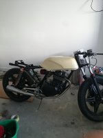
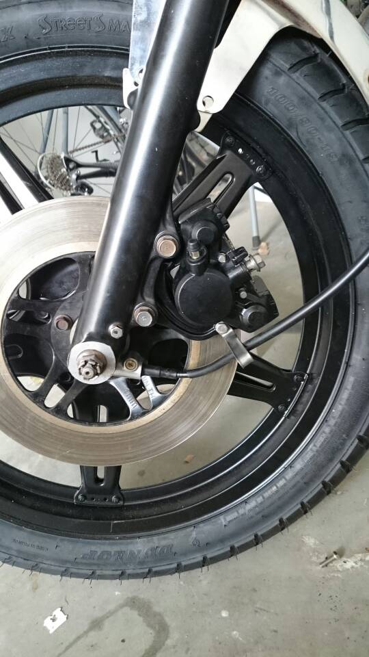
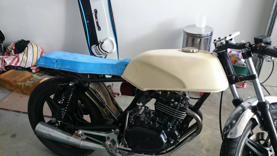
Got tired of seeing the empty frame so bolted the engine back in, turns out it was actually much easier without the head on. The old seat foam just sitting on top of the frame looking for inspiration. Picked up an old front fender at the same time as the old 250N calliper for $20. Made up some alloy blocks to fit the fender to the forks and gave it a bit of a trim to fit the tire properly.
Roughed up a speedo mount as well. Approximate representation of the gauge drawn on.
The fender initially: looks like it was meant for a smaller wheel/tire.

After a bit of adjustment (still needs tidying up):

The mounting blocks:

The intake valves after being ground:

Nothing more satisfying than a fresh piston and bore:

Very roughly cut mount:

Got tired of seeing the empty frame so bolted the engine back in, turns out it was actually much easier without the head on. The old seat foam just sitting on top of the frame looking for inspiration. Picked up an old front fender at the same time as the old 250N calliper for $20. Made up some alloy blocks to fit the fender to the forks and gave it a bit of a trim to fit the tire properly.
Roughed up a speedo mount as well. Approximate representation of the gauge drawn on
. The fender initially: looks like it was meant for a smaller wheel/tire.
After a bit of adjustment (still needs tidying up):
The mounting blocks:
The intake valves after being ground:
Nothing more satisfying than a fresh piston and bore:
Very roughly cut mount:
chrisbchips
New Member
I got lucky this week, was on call for work but no call in!
chrisbchips
New Member
Progress! New intake valves arrived so finished putting the engine back together. Was a bit nervous as it's my first automotive engine rebuild, the entire project was hinged on this thing starting again! Belly full of oil, some fresh fuel and spark plug, and away she went on the second kick! Couldn't be more thrilled.
Now on to the fun stuff- new shocks on the way, tank is sitting ready in primer, and the fiberglass is setting on the seat. Seeing the tank in beige actually gave me a bit on inspiration for the colour. I had intended on finishing the tank in teal, but might have to give it a bit more thought.
Question for the electronic guru's: I was very keen to install a battery eliminator (I know it's a general rookie mistake). However all the lights on this bike will be LED, and it's a kick start only with separate stator windings for the ignition. When it was running I took the opportunity to measure the output from the Rectifier/Regulator but it's putting out around 30-40VDC at idle?
I figured my regulator was junk so went and picked up another one, exact same result?? I'm guessing without the load of charging a battery the regulator can't sink all the power? When I attach the capacitor for the battery eliminator, what's stopping it from sending 30-40v to the lights and blowing them?
Chris B.
Attachments
chrisbchips
New Member
Might be on to something there Brodie - I did sand down to bare metal, but at the moment the only ground point I have is the one where the coil attaches. Perhaps it's prudent to make another ground attachment somewhere else on the frame? I did check the ground continuity with my multi-meter and it seemed alright, but it would definitely explain the problem.
chrisbchips
New Member
Hmmm, double checked the harness, looks like it was definitely earthed, although just through the one point, the same point as the coils. Is it possible this was not a sufficient earth for the low voltage system?
chrisbchips
New Member
Solved the electrical issue - the wiring harness is a bit of a mess and there was a broken line halfway down that connects the regulator/rectifier to the ignition switch. Re-connected and we have a nice steady 14.7v.
Braided brake lines arrived, so bled the brakes which turned out to be a non event.
Fitted the new sprockets after deliberating about their size and fitted the new chain as well (not without drawing a bit of blood trying to remove the clip on the master link).
Made myself a seat pan using fiberglass with some reliefs to accommodate the frame and electronics. Never going to attempt that again, next time I'll be paying a professional. There's an art to cutting and manipulating foam I just don't have. The upholster covered a multitude of sins!
Speedo arrived promptly as well so thats mounted. Printing off a few clips and mounts with the 3d printer as we speak!
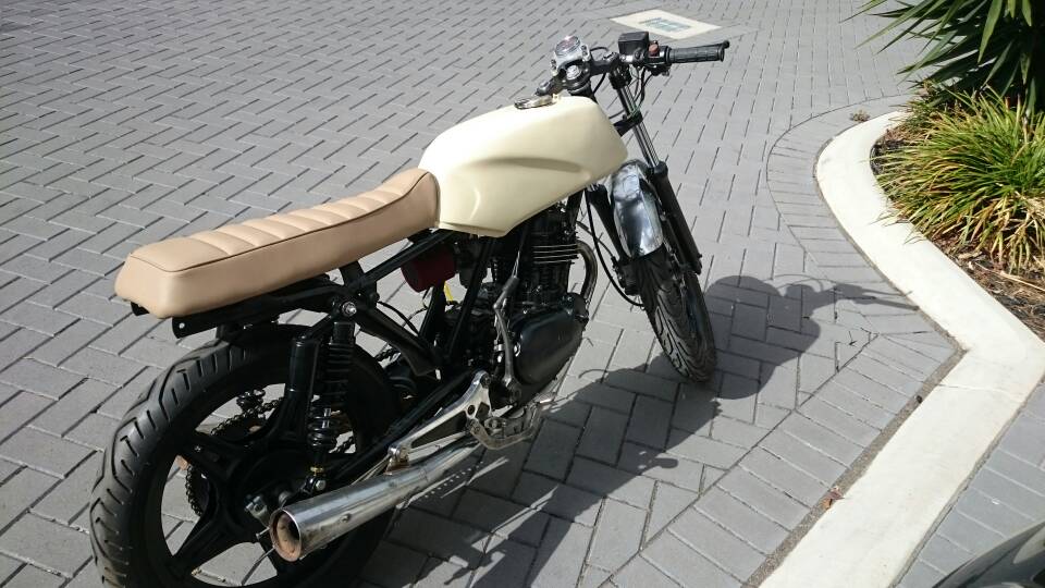


