Follow along with the video below to see how to install our site as a web app on your home screen.
Note: This feature currently requires accessing the site using the built-in Safari browser.
We noticed you are blocking ads. DO THE TON only works with community supporters. Most are active members of the site with small businesses. Please consider disabling your ad blocking tool and checking out the businesses that help keep our site up and free.
Also a question on the headlight wiring. I have the headlight connected to the run switch so that hopefully its only really operated with the motor running.
The headlight has a smaller bulb holder (with no bulb in it currently), is it customary to have a small low wattage bulb in this as a side light for when the ignition is live?
I can't remember but I think the diode prevents grounding if it isn't in neutral until you pullclutch in.
I haven't done Honda electrical course since 1980
Found this on SOHC4.net
http://forums.sohc4.net/index.php?topic=69712.0
I can't remember but I think the diode prevents grounding if it isn't in neutral until you pullclutch in.
I haven't done Honda electrical course since 1980
I thought that the neutral switch was grounded only if in neutral hence the diode isn't really required. Funnily enough I just looked in a 350-400 service manual and the diode isn't on any of the circuits. Maybe it was a different year thing.
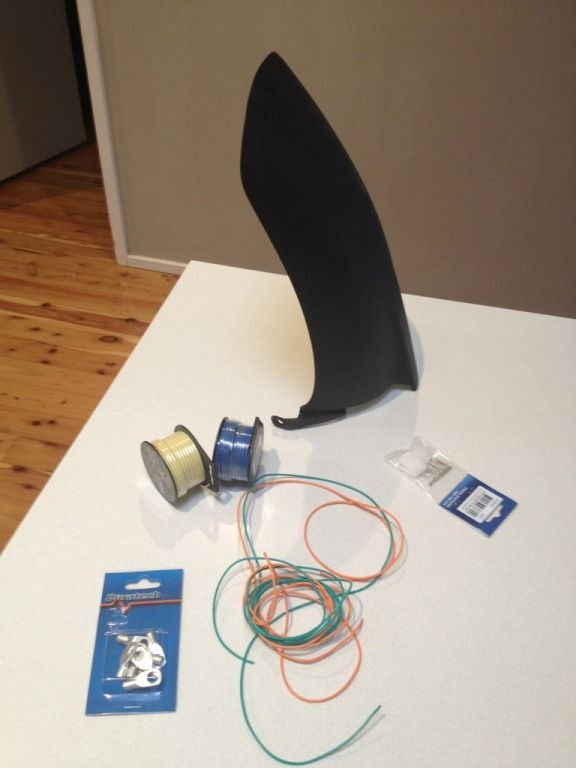
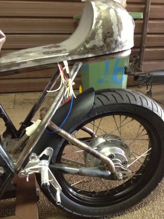
Bought last of the electrical bits yesterday so I should have the harness ready to rock and roll by the end of this weekend. Also excited to receive my hugger from a breakers in the UK via the power of eBay. It's from an Aprillia RD125 and looks like it might work ok:
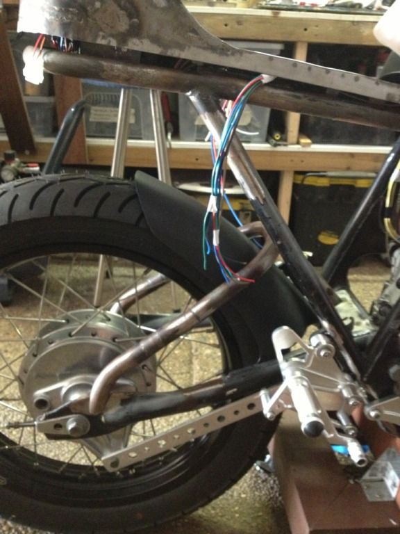
Couldn't resist getting into the shed and test fitting the hugger. Turns out the original mounts aren't going to work as they are asymmetrical. A quick go with the grinder, a tidy up on the belt sander and its much closer:
It's still not perfect, I've got to take a bit more material off the front edge to address the angle it sits on the swingarm but I'm quietly confident its going to sit well and also fit within the swingarm brace.
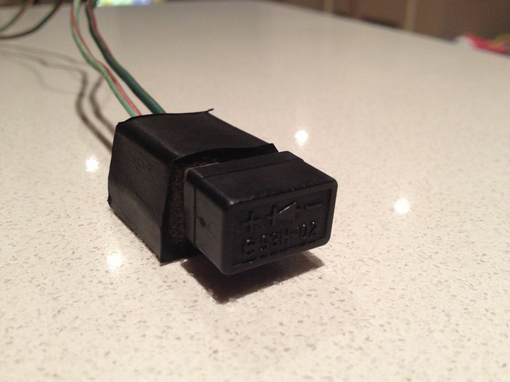
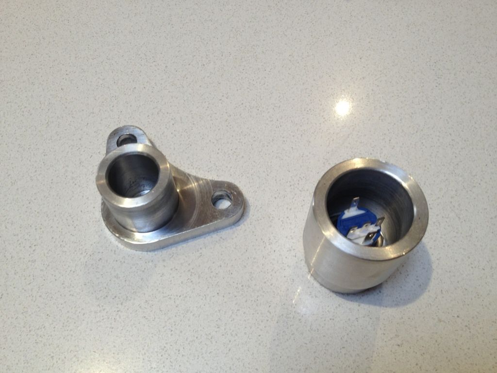
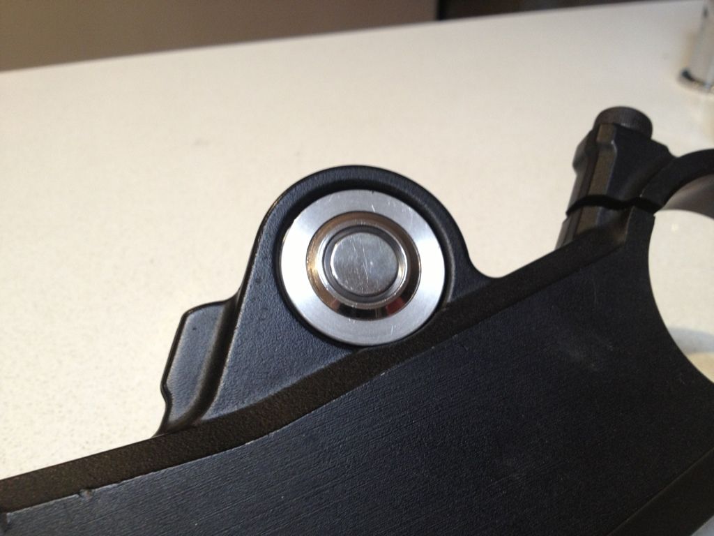
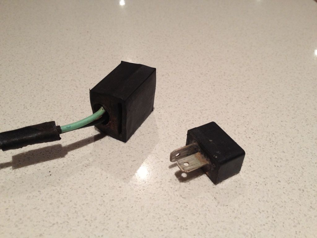
Also just pulled the diode (logic circuit) off the old loom with a view to using it on the new wiring, simply because a new one is a fortune and simply not worth it. The logic circuit sits on the earth side of the starter solenoid and I assume stops bleed between the neutral and clutch switches. This is a safety feature to stop you starting the bike in gear and something I kept (despite being a complicated circuit) just in case it was required for a roadworthy certificate. The original had a pleasant surprise, it came with a rubber mount which will work really well to create a mount on the battery box:
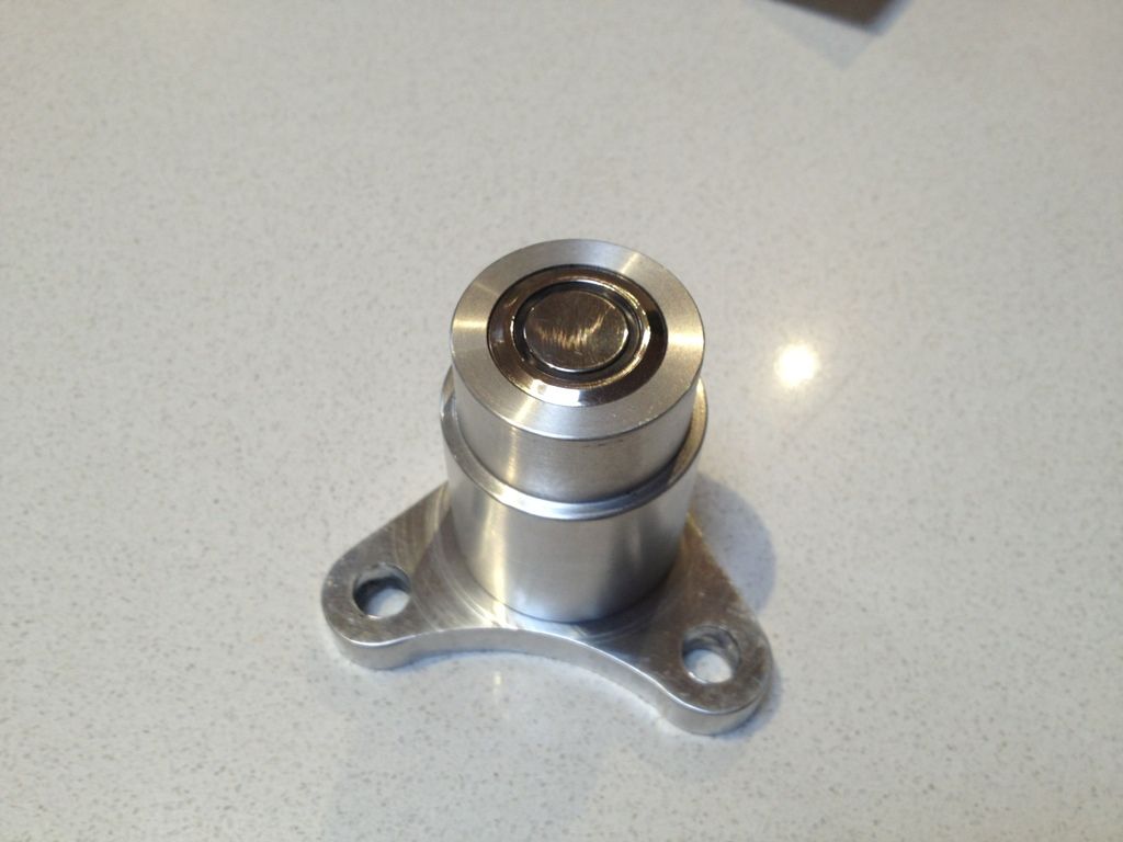
A little scrub with the kitchen sponge and it came up pretty nice:
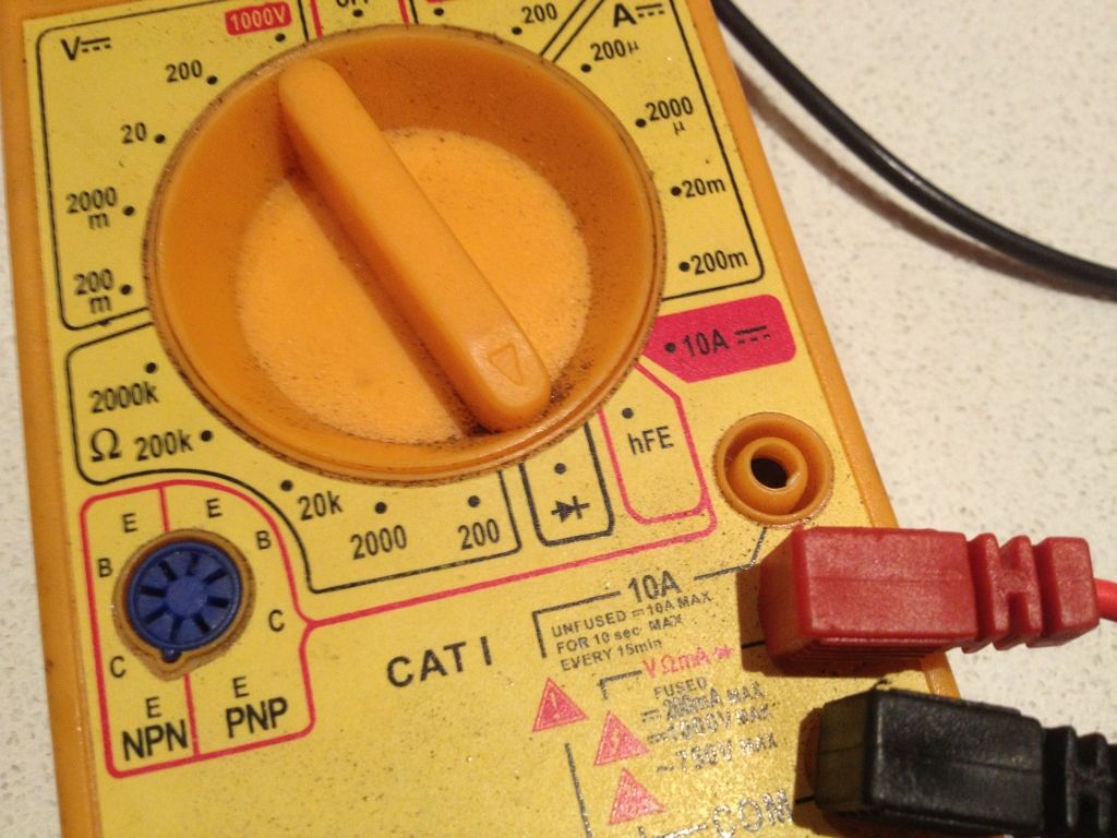
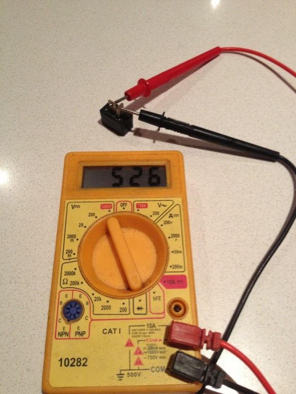
Thought I would grab the tester and see if it actually worked. First try was resistance and it turned up nothing in either polarity... bollox!
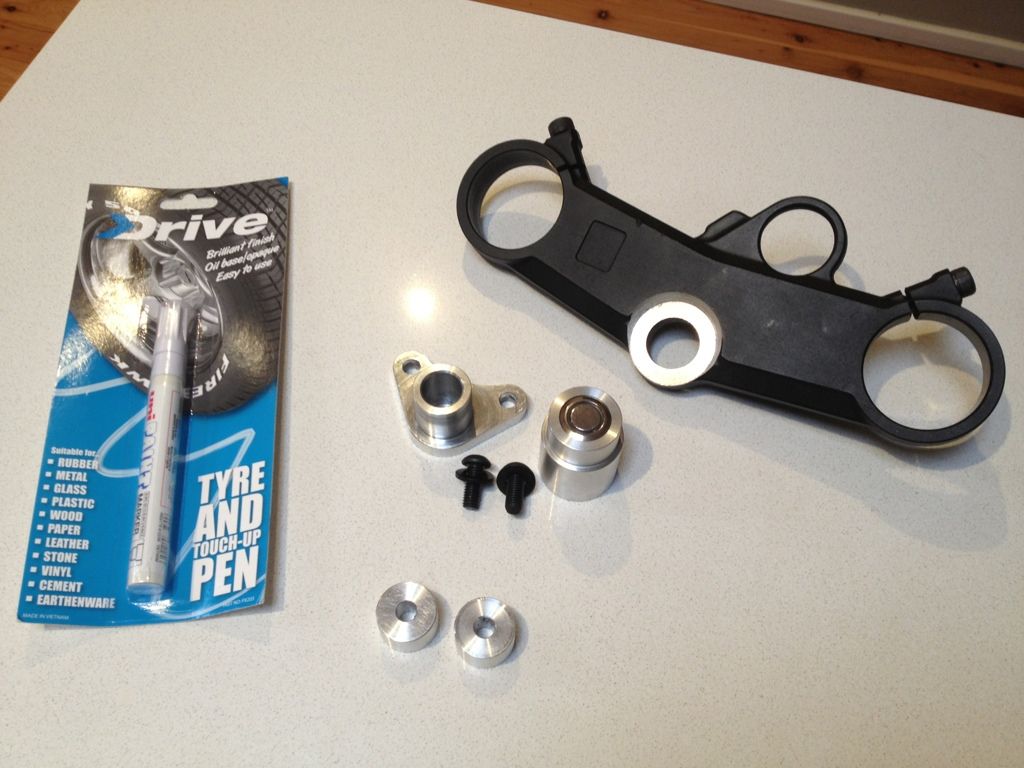
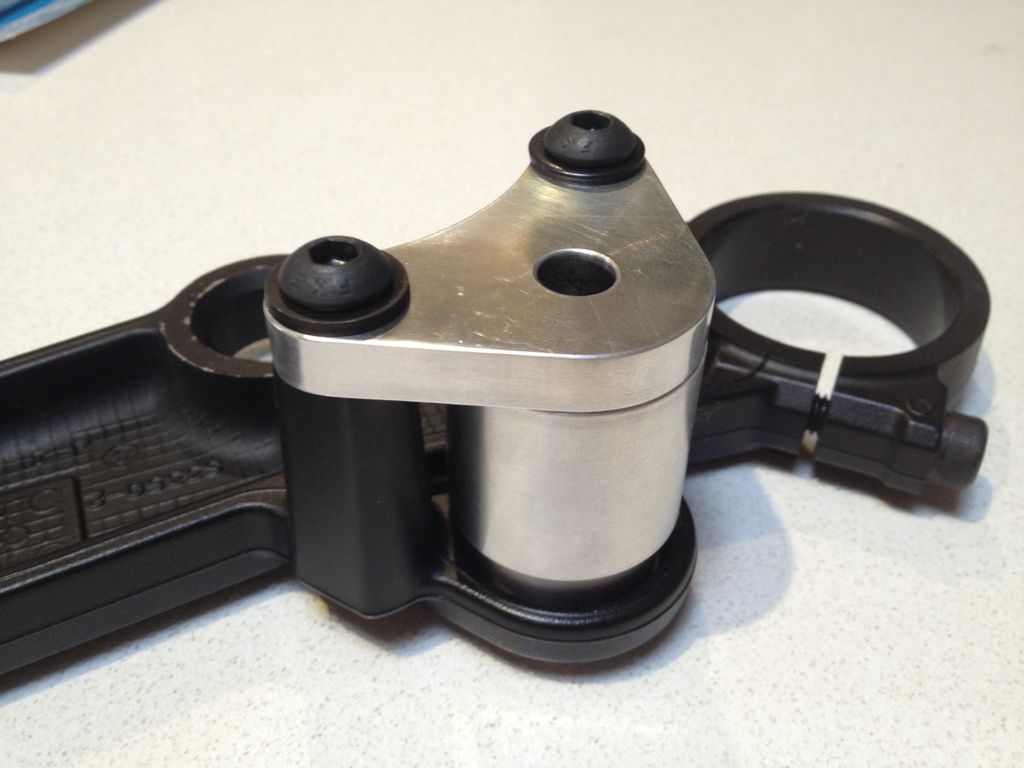
Just pulled the trigger on the latest big purchase. Not only is the item top shelf but the people involved are top shelf too. It represents a big milestone in the build:
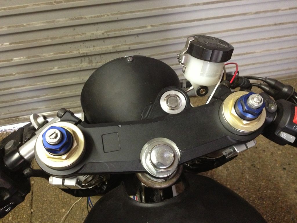
Went and picked up some bits from my bud Darren at DNA Customs, the remainder of the rearset spacers and a custom button holder I'd had made to accommodate the wireless ignition switch button. In the end it worked out beautifully and should look pretty factory once complete.
Already testing some of the wiring as I'm planning on running the LEDs in the switch as an indicator the RFID has been activated and also when the ignition is active. Seems to be working ok.
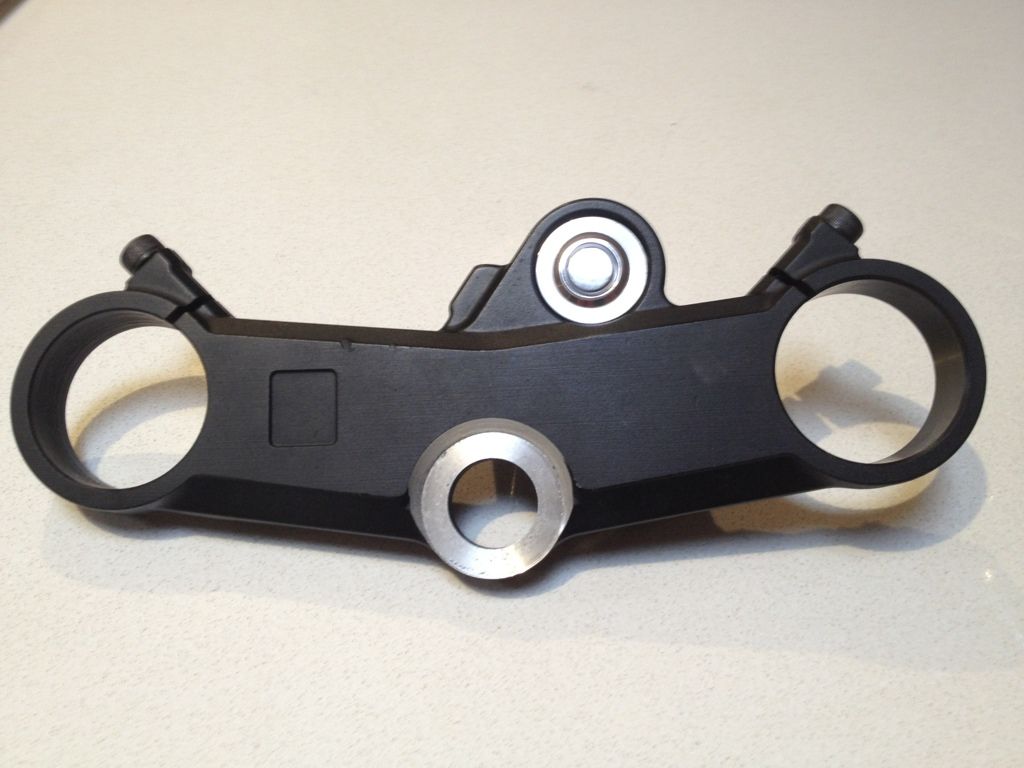
Gratuitous pics:
And of course one on the bike. I will grab a video of it all working when I finally get the wiring finished:
The joys of owning a CNC. I gave some design direction but Darren did the rest, there are some sweet little touches like slightly recessing the button and the sweeping bottom mount. I'm quite pleased with how its turned out!
Looks great man! I have a spot on my CBR1000 triple, hopefully it comes out as clean and professional as yours! Can you take a few shots of your grips in total view and a side shot of that frontend? I really like those blue fork tops man.
So I think I have a problem with my electrics. Finishing up and doing some testing and had an issue with the RFID.
I've run a power feed in line with the RFID's LED (the one to show it functional), problem is I think its run power back into the RFID and now its not working (bugger)!
Should be a simple fix as I will just run some diodes to stop any current leakage back up into the RFID. Fingers crossed.
I do have another problem that I'm not sure how to fix though. To stop the RFID running a parasitic draw on the battery I've put a simple switch in line with its power feed. Problem is that when the switch gets turned back on it seems to send a pulse to the relay (probably because the circuitry is a bit basic) turning it on.
This is less than ideal as simple turning power on for the RFID essentially powers up the bike without having to use the key fob.
This site uses cookies to help personalise content, tailor your experience and to keep you logged in if you register.
By continuing to use this site, you are consenting to our use of cookies.

") and it came up pretty nice:
and it came up pretty nice: