
We noticed you are blocking ads. DO THE TON only works with community supporters. Most are active members of the site with small businesses. Please consider disabling your ad blocking tool and checking out the businesses that help keep our site up and free.
You are using an out of date browser. It may not display this or other websites correctly.
You should upgrade or use an alternative browser.
You should upgrade or use an alternative browser.
'81 CB750C "Rock-It" (X-Basket Case)
- Thread starter Hoosier Daddy
- Start date
Hoosier Daddy
Earache my eye...
Sure is Pete! Seems like a major milestone as far as progress goes. For the longest time it has felt like I was just doing small tasks while waiting. All value added but nothing that really showed forward movement.
I kept finding myself looking over at the BSA :")
I kept finding myself looking over at the BSA :
Lookin sweet HD 8) real progress i know that feelin too guess ive hit the wall again ??? tank n seat unit to go then tweakin motor all there is between workshop n the open road keep goin mate soon be out on the open road
i know that feelin too guess ive hit the wall again ??? tank n seat unit to go then tweakin motor all there is between workshop n the open road keep goin mate soon be out on the open roadSilkySmooth750
What does "Personal Text" mean?
v-pilot said:OMG! looks F#&%in' awesome ;D
What he said.
Hoosier Daddy
Earache my eye...
Thanks all... much appreciated!
Hoosier Daddy
Earache my eye...
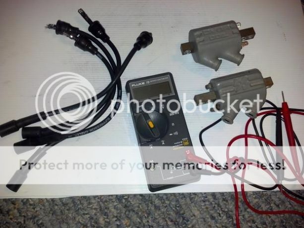
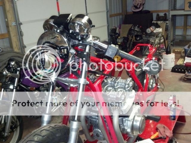
Holy Cow... been posting on other peoples threads here and neglecting my own! So to get this up to speed here is what I've done recently... It's been cold AND damp here lately, so I've been working on the small stuff I can bring in the house.
Cleaned and tested the Dyna coils that were in a box of parts, need new wires but the coils are fine.
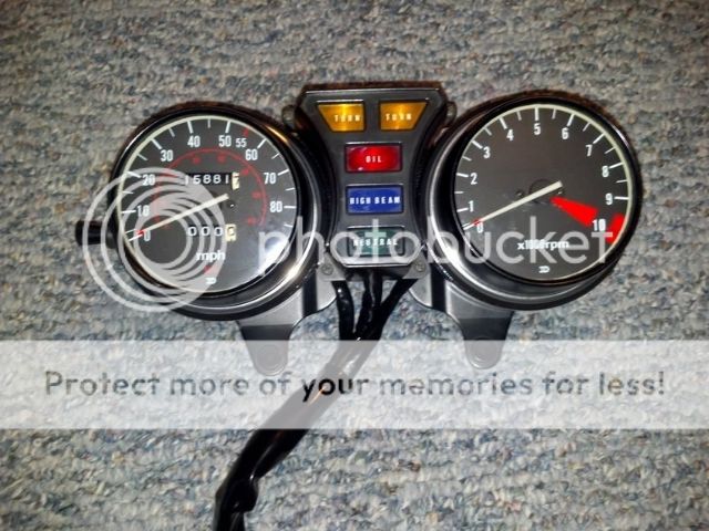
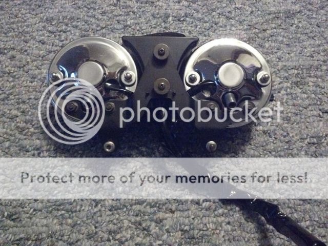
Brought the clocks in and disassembled, cleaned and checked all the bulbs. Reassembled them and should be good to go.
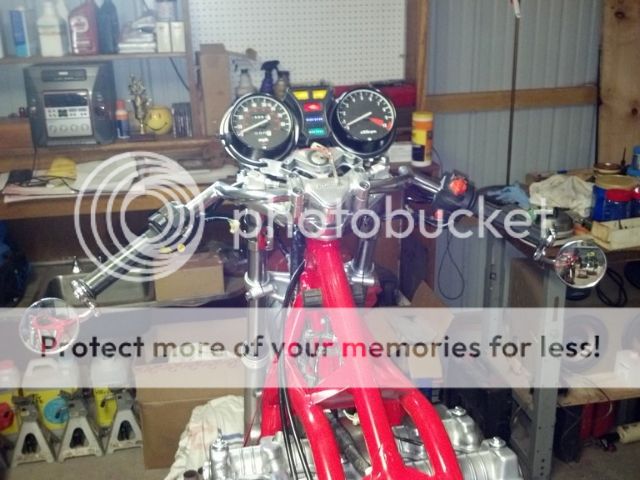
Next, the main harness got the same treatment, plastic safe electrical contact cleaner on all the connectors and a good inspection, then routed it in place. Installed the gauge pod, ignition switch, cut the grips, and got the bar-end mirrors on.
Also had a slight set-back, I've been working on fitting the Ebay'ed NOS Mac side outlet mufflers to the factory tubes.
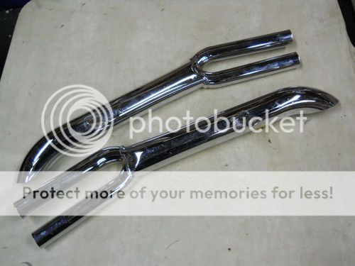
Only to find the right side looks good, but the left must have gotten tweeked over the years. On that side, (top in the pic) you can see the inlet tubes taper together towards the front. They pinch too close together and don't line up to the headpipes, also up against the frame and no room for the side stand at all. Looks to me like if the inlets on that side were parallel like the right they would work. Need to hash out a way to bend them back without kinking them or fucking up the chrome... :
Cleaned and tested the Dyna coils that were in a box of parts, need new wires but the coils are fine.
Brought the clocks in and disassembled, cleaned and checked all the bulbs. Reassembled them and should be good to go.
Next, the main harness got the same treatment, plastic safe electrical contact cleaner on all the connectors and a good inspection, then routed it in place. Installed the gauge pod, ignition switch, cut the grips, and got the bar-end mirrors on.
Also had a slight set-back, I've been working on fitting the Ebay'ed NOS Mac side outlet mufflers to the factory tubes.
Only to find the right side looks good, but the left must have gotten tweeked over the years. On that side, (top in the pic) you can see the inlet tubes taper together towards the front. They pinch too close together and don't line up to the headpipes, also up against the frame and no room for the side stand at all. Looks to me like if the inlets on that side were parallel like the right they would work. Need to hash out a way to bend them back without kinking them or fucking up the chrome... :
Hoosier Daddy
Earache my eye...
Yeah that's what I was thinking, tried it for a short time with a piece of pipe in the vise but not REAL hard, didn't want to kink it or flare the end...
Next thing is... How in the HELL did that picture get swapped? The LEFT is the one thats tweeked.. but that pic sure looks like the right. If my left looked like that left in the pic, I'd be golden... but then the right would be the one tweeked.
Next thing is... How in the HELL did that picture get swapped? The LEFT is the one thats tweeked.. but that pic sure looks like the right. If my left looked like that left in the pic, I'd be golden... but then the right would be the one tweeked.
Maybe u could use a bit of heat on em when u tweak em mite help mate clocks look well are they originals really had to fettle mine lot cheaper than replacements tho she's coming on hoos definitely a head turner lookin forward to the finish mate 8). On a go slow here at the moment weather still pants n waiting for the snow to clear to get her finished one day the wheels will turn :-\
Hey Hoosier, what kinda handlebar clamp do you have going on there. Looks sweet!
Hoosier Daddy
Earache my eye...
Thanks Canyoncarver , it's the stock C model clamp that I stripped and polished.
and yea Yorkie, they are stock clocks as well.
I'm a cheap bastard if I can get away with it.
and yea Yorkie, they are stock clocks as well.
I'm a cheap bastard if I can get away with it.
v-pilot
More Fun At The Ton!
Looks to me like you're Mayhem ;D ;D ;DHoosier Daddy said:I'm a cheap bastard if I can get away with it.
Hoosier Daddy
Earache my eye...
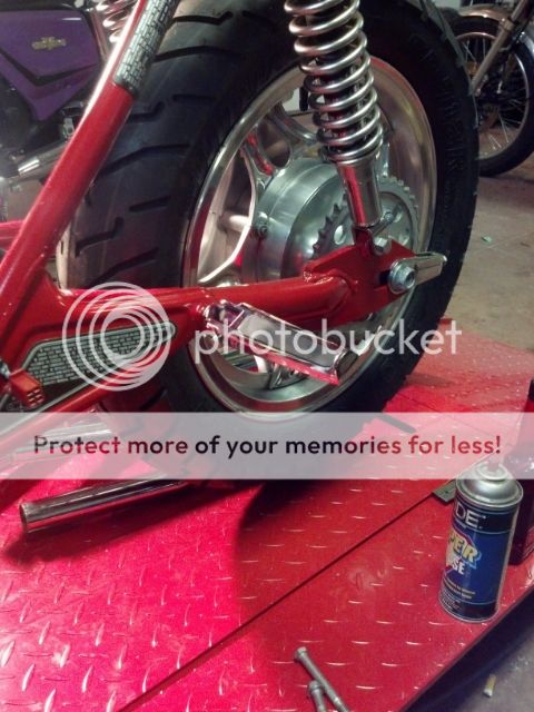
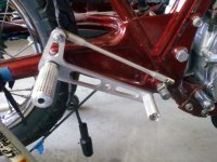
Moving onto the rearsets, I have done a lot of searching in that section of the forum. Learned quite a bit and had a good idea of what I wanted. Contacted Teazer for insight on placement. Then found these pegs on the "sale rack" at the local dealership and they were close enough to what I have rolling around in my head, polished aluminum with rubber inserts... I tried them in the passenges peg location for personal fitment.
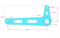
Since I am building my own seat, I can adjust the height of my bum if needed but I think these are going to work out well here. So next, I found a drawing that I could tweek and change the dimensions on in this old thread.
http://www.dotheton.com/forum/index.php?topic=7056.0
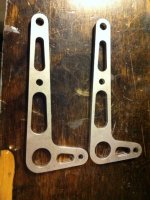
Moved some speed holes and took out the meat in between to turn them into slots. Here is what I have come up with. May not even be close to the finished product, as we all know, but at least it's a guide. Picked up some bronze bushings and spacers that fit the mounting bolts for the pivots.
Since I am building my own seat, I can adjust the height of my bum if needed but I think these are going to work out well here. So next, I found a drawing that I could tweek and change the dimensions on in this old thread.
http://www.dotheton.com/forum/index.php?topic=7056.0
Moved some speed holes and took out the meat in between to turn them into slots. Here is what I have come up with. May not even be close to the finished product, as we all know, but at least it's a guide. Picked up some bronze bushings and spacers that fit the mounting bolts for the pivots.
Attachments
biker_reject
Over 1,000 Posts
Hoosier Daddy
Earache my eye...
biker_reject your build thread is one of the several that I read while researching info, and honestly your comment on if you had it to do over you would go with fastfromthepast weighed real heavy on my mind!
I already had the plate alluminum, and when I found the pegs on sale decided I'd give it a try. I will probably go to them for the shift and brake arms, also saw the DCC univeral linkage kit, but the linkage rod, heim joints, clevis, and jam nuts I can source locally.... I need to make up a BOM and do some price comparison.
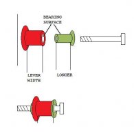
Also I am torn on using one or two bronze bushings. So far I have bought one (green), but realize when I draw down the mounting bolt it will pinch the bushing and the bearing surface will be a slip fit between it and the aluminm lever. Where if I buy the next size (red) and press it into the lever, then have the original (green) slightly longer, would allow me to draw down the mounting bolt tight to keep the foot peg in place and the beaing surface will be between the two bushings with the lever still moveing freely.
I already had the plate alluminum, and when I found the pegs on sale decided I'd give it a try. I will probably go to them for the shift and brake arms, also saw the DCC univeral linkage kit, but the linkage rod, heim joints, clevis, and jam nuts I can source locally.... I need to make up a BOM and do some price comparison.
Also I am torn on using one or two bronze bushings. So far I have bought one (green), but realize when I draw down the mounting bolt it will pinch the bushing and the bearing surface will be a slip fit between it and the aluminm lever. Where if I buy the next size (red) and press it into the lever, then have the original (green) slightly longer, would allow me to draw down the mounting bolt tight to keep the foot peg in place and the beaing surface will be between the two bushings with the lever still moveing freely.
Attachments
Hoosier Daddy
Earache my eye...
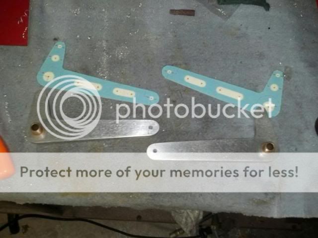
Decided to go with one bronze bushing with shoulder and a washer on the other side that had an ID to fit the 3/8" peg bolts and their OD was just under 1/2" at .490"
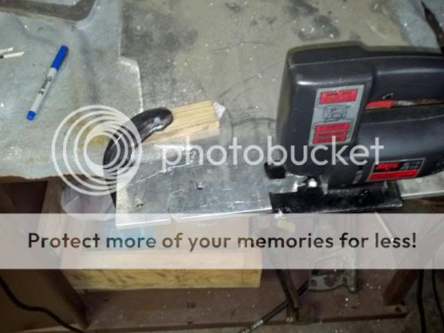
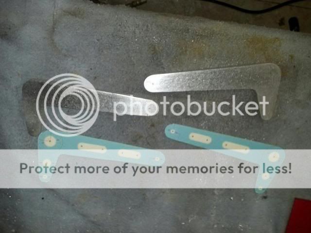
Printed and cut out the pattern onto some cardstock and transfer that onto my 3/8" aluminum plate.
Then came the tedious sawing of the aluminum with my jig-saw. Slow and stready, several pie cuts and radius holes to get the curves close... I need to buy a band saw.
...and the rough cut pieces.
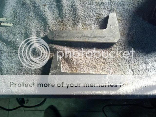
Then I transfered the holes with my auto-punch. Notice I made both a right and left pattern that allowed me to draw the patern and transfer to holes on both pieces easily so I'd be sure to be cutting / drilling from the back side, hate to marr the good sides nice finish.
Then onto the drill press. I used a 13/64" drill bit, both for the pilot holes of the pivot and to have the right size to tap the toe peg holes to 1/4-20. then drilled the pivot holes out to the 1/2". Changed to a drum sander to clean the rough edges, best way for me with my limited equipment to get in the radius.
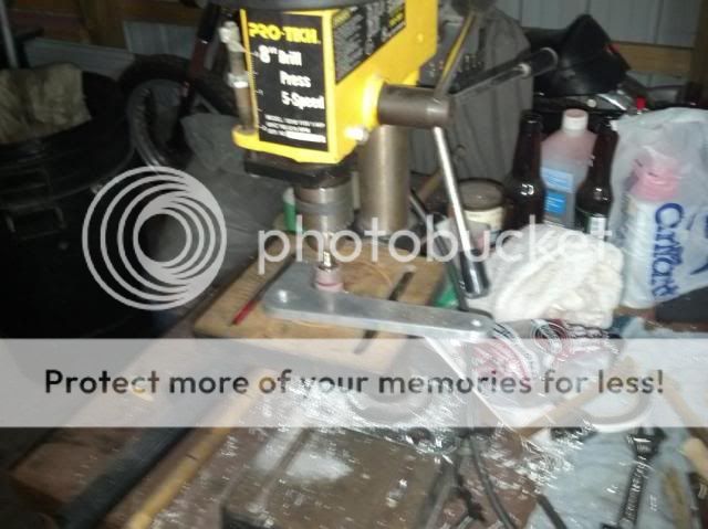
Next a little clean up with a rolled up piece of scotchbrite and a dab of oil in the pivots, I fit the bushings.
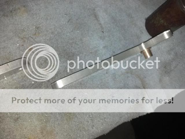
Here's and edge shot to show hole the drum sander cleans up the rough cut edge. Key is to keep it moving, don't stop in one spot to long...
Coming up I plan to get 1/4-20 shoulder bolts and hose for the toe pegs. Then the clevis and heim joints along with rod to thread for the linkage, once those are in hand I will drill the remaining holes. Hate to guess on the size of that hole size now and risk messing up.
So more to come...
Printed and cut out the pattern onto some cardstock and transfer that onto my 3/8" aluminum plate.
Then came the tedious sawing of the aluminum with my jig-saw. Slow and stready, several pie cuts and radius holes to get the curves close... I need to buy a band saw.
...and the rough cut pieces.
Then I transfered the holes with my auto-punch. Notice I made both a right and left pattern that allowed me to draw the patern and transfer to holes on both pieces easily so I'd be sure to be cutting / drilling from the back side, hate to marr the good sides nice finish.
Then onto the drill press. I used a 13/64" drill bit, both for the pilot holes of the pivot and to have the right size to tap the toe peg holes to 1/4-20. then drilled the pivot holes out to the 1/2". Changed to a drum sander to clean the rough edges, best way for me with my limited equipment to get in the radius.
Next a little clean up with a rolled up piece of scotchbrite and a dab of oil in the pivots, I fit the bushings.
Here's and edge shot to show hole the drum sander cleans up the rough cut edge. Key is to keep it moving, don't stop in one spot to long...
Coming up I plan to get 1/4-20 shoulder bolts and hose for the toe pegs. Then the clevis and heim joints along with rod to thread for the linkage, once those are in hand I will drill the remaining holes. Hate to guess on the size of that hole size now and risk messing up.
So more to come...
biker_reject
Over 1,000 Posts
Yes! The drum sander. I find those things indispensable. Your set sure turned out nicer than mine! My first attempt looked like something out of the Flintstones.


