Suzuki GS650GL cafe project

I'm not quite sure yet HD. The original seat mounting bracket is under there, and it actually is in a great location for mounting a tail light, and for extra mounting of the tail piece. In the ends of the tubes I had though of mounting some tiny round lamps for signals. But I've thought of doing a hoop too. Havent quite made up my mind there.
 
Spent a couple hours in the shop this morning and got alot done. I went to work de-tabbing the battery area under the seat and getting it cleaned up. I also lobbed off the rear section of the frame. I think I will do a loop of some sort.
After I had the area cleaned up I set to work building a mounting system for the battery carrier. I found some 1/2X1/2 square tubing at work in a scrap bin and snatched it up for this.
I only had time to get the top front tacked into place, but it will have a piece run across the back (in front of the rear tire), and a bracket that will go down off the left front bottom corner to a stock crossmember tube.
I wanted to stay with a conventional, larger battery size mainly due to the accessabiltiy of such a battery should this one go kaput on the road. It is heavy, but I've tried to place it in a central position and as down low as I can. I may play with spacing the battery down a little to get the weight even further down low.
Above the battery I'll build a tray for the electrical stuff to sit.
 

Attachments

  • PA250205.JPG
    PA250205.JPG
    99.8 KB · Views: 228
  • PA250211.JPG
    PA250211.JPG
    94.1 KB · Views: 255
  • PA250217.JPG
    PA250217.JPG
    77.8 KB · Views: 232
  • PA250219.JPG
    PA250219.JPG
    96 KB · Views: 240
a couple more
 

Attachments

  • PA250214.JPG
    PA250214.JPG
    67.4 KB · Views: 219
  • PA250229.JPG
    PA250229.JPG
    56.3 KB · Views: 945
Still working on the battery box today. This thread is starting to get windy. I dont like to get so detailed, but I just cant help myself. I appreciate detailed build threads from others so I can see how they might do things.
I pretty much got the basics of the battery carrier lined out yesterday, today was just about the details.

The pics are pretty self-explanitory on this one.
 

Attachments

  • PA260214.JPG
    PA260214.JPG
    83.1 KB · Views: 225
  • PA260212.JPG
    PA260212.JPG
    86.6 KB · Views: 232
  • PA260209.JPG
    PA260209.JPG
    97.2 KB · Views: 224
  • PA260206.JPG
    PA260206.JPG
    87 KB · Views: 231
a few more to give you a better idea of the battery placement. I'd have liked to have mounted it lower in the frame, but accessability was one of my goals, so I wanted to keep things pretty simple. As I said in an earlier post, I want to build a tray for the other electrical equipment above the battery. I think instead I'll make a plate, X-shaped that will go above the battery carrier that the electrical things can bolt to. Above that I think I'll have room to build a removable storage tray for fuses, registration, spare plugs, tool kit, etc.. There is also ample room on the right side of the battery for a small storage area if I like.

I'm also going to relocate the rear master cylinder resorvior from the frame tube to the corner of the battery carrier. This will make it tuck inside the frame so that an aluminum side panel can be made to cover the area.
 

Attachments

  • PA260215.JPG
    PA260215.JPG
    92.3 KB · Views: 227
  • PA260216.JPG
    PA260216.JPG
    105.1 KB · Views: 246
I went out to clean the shop today and ended up doing some work on the 650. I made a template from scrap cardboard for the electrics tray. From the same piece of steel shelve I had I cut out the shape of the template. A little clean up work, a hole to access the top battery cage mounting bolt. I think I'll drill some large holes in it for looks and lightening, and will back-weld nuts for mounting the R/R and other electrical equipment.
The large notch along the right side of the plate is for access to the rear master cylinder res.. I'm going to cut the mounting tab off the frame and weld it to the rear right corner of the battery cage so that it tucks inside the side panels.
 

Attachments

  • electrics tray template.jpg
    electrics tray template.jpg
    41.1 KB · Views: 599
  • electrics template mocked2.jpg
    electrics template mocked2.jpg
    49.3 KB · Views: 615
  • electrics tray roughcut.jpg
    electrics tray roughcut.jpg
    22.8 KB · Views: 633
  • electrics tray finished.jpg
    electrics tray finished.jpg
    45.1 KB · Views: 652
more of the "finished" piece. It will weld to the frame.
 

Attachments

  • electrics tray finished3.jpg
    electrics tray finished3.jpg
    41.8 KB · Views: 664
  • electrics tray finished4.jpg
    electrics tray finished4.jpg
    38.2 KB · Views: 649
  • electrics tray finished2.jpg
    electrics tray finished2.jpg
    44.6 KB · Views: 630
Ok, I decided my lightweight electrical tray was TOO lightweight. The steel shelving material I used is great, but without some beads rolled into it to strengthen it, it's a little flimsy. I have a big sheet of 1/8 inch steel plate and opted to make it out of that instead.
So tonight I remade it, and yes it's heavier, but this thing isnt an all-out racer anyway. This is strong and reliable...qualities I've come to appreciate from a motorcycle.
After cutting the shape out with my grinder I mocked and clocked all the pieces that need to mount to it. Once I found a pleasing arrangement I marked everything and drilled holes for mounting screws. I then back-welded all the nuts for easy removal of the equipment. The large hole is for all the wires to feed down through. I'm hoping one of the large rubber grommets in the back of the headlight housing will fit this hole. If not I'm sure I can locate something that will work so the wires dont get chaffed on the edges of the hole. I like it!
 

Attachments

  • PA300207.JPG
    PA300207.JPG
    68.6 KB · Views: 234
  • PA300209.JPG
    PA300209.JPG
    63.5 KB · Views: 231
  • PA300210.JPG
    PA300210.JPG
    88.7 KB · Views: 278
Liking where this is going. Don't worry about your thread being too windy, part of the joy of reading build threads is seeing the builder's though process as he tries to figure something out, if this or that will work or not. (I like your idea of relocating the rear brake master cylinder after discovering mine is rotted out from the inside, ergh!)

If you can't find a rubber grommet for the wire bundle hole in your tray, you might want to try some automotive door edge trim.. self adhesive and shaped perfectly for this kind of application..
 
Thanks Seaking. Yes, I agree...I like to see every step in a builders process...helps me figure out my own process. Plus I cant figure out how to post more than 4 photos per post, so I end up replying to my own posts alot! I need to use photobucket, but I hate it, so this works.
Yes, I thought of the same edge trim for the hole. I'm sure I'll be able to find a grommet to fit the hole. I am going to use some of that edge trim for other areas of the bike.
The master cylinder res. will be more difficult to access once I move it, but it's not like you need to get at it every day. Plus I want to make the seat easily removable, and there will also be a side panel for access. My plan from the onset is to just simplify the whole bike, and in the process give it some cafe racer style. Thanks for the comments!

PS: I have a rear master cylinder for a KZ1000 with an integrated resorvior if you're interested. I was going to adapt it for this bike, but since I'm not using rearsets it would have meant too much changing around of that whole assembly. PM me if you're interested.

http://www.dotheton.com/forum/index.php?action=dlattach;topic=54508.0;attach=102021;image
http://www.dotheton.com/forum/index.php?action=dlattach;topic=54508.0;attach=102023;image
 
Many thanks, M8.. I didn't realize parts were 'interchangeable' like that.. I need to find a cross reference list or something for such things.. I know people have used Honda R/R to replace the Suzuki one.. that's about all I know thus far.. ;) slowly but surely!

I'm pulling the front brakes off today to see what they look like.. feels like it's building pressure....
 
Thanks Noob! I'm kinda outta my realm with this thing...I'm a Harley guy at heart, but this thing is fun for sure.

Seaking, anything can be made to fit anything else. This M/C would be an easy conversion though. It's just a tab on the brake lever that pushes on the rod on the M/C. The hardest part would be finding an appropriate mounting location that keeps the resorvior level and keeps the geometry of the rod correct. Were I making full-on rearsets and messing with all that shit I'd keep it and run it, but I'm not, so I don't need it. The rest of this bike is long gone, so I'm just trying to get rid of the misc. parts I have left.
 
Understood.. I have a bunch of left over bike parts from my previous bikes that can be adapted to any bike.. I have to start thinking outside the box again ;) Thanks for sharing!
 
You bet. For me that is most of the fun of a build...actually building parts and pieces, but also finding a way to make other parts from other machines fit the one you're working on. Maybe you have a taillight that would really suit your current project, or maybe it's something else. I've been staring at a small brass pitcher my wife gave me trying to figure a way to make it work as a cool taillamp housing. One of the coolest air cleaner covers I've ever seen was the top off a 1950s era Juice King juicer (Caleb Owens, Uncle Sam). Nothing is beyond the realm of possibility, it's just a matter of adapting that part to work for you. I'm not saying I'm a master at this, or even good at it, but I am a believer that any part you make or modify to use on your motorcycle should be beautiful.
 
I've seen some genius use of items not meant for motorcycles find their way onto bikes in the past... Beauty in the eye of the beholder etc.. ;)
 
I got a good deal of work done yesterday. In addition to working on wiring harness info for Sonreir, I got some shop time to finish the tank mounting setup and relocate the rear M/C res.
I like the mounting location of the resorvior, but it is leaning outward a bit more than I'd like. I may play with that a little.
For the back tank mount I used a piece of halfXhalf steel tubing spanned across the frame tubes. I keep all the tabs I cut off of projects, and I used a couple of those to mount it up. I utilized part of the stock mount on the back of the tank, and this one was a bugger. I had to remake it a couple times, but finally got it to work. It's not ideal in my opinion, but it works good and is solid.
The front mount was easy by comparison. I just bent and drilled a piece of 1/8 inch steel plate, drilled a hole into the backbone and welded a stud in there, slipped it all together, and there it was.
I was concerned that the tank may want to wobble from side to side with the 2 centerline mounts, but it's solid as a rock! Even with the rubber doughnuts I used at each mount it's really secure. I'll clean all this stuff up too before paint, so for now it all looks a bit rough. Dont worry...I'm not done!
 

Attachments

  • tankmountfront.jpg
    tankmountfront.jpg
    56.2 KB · Views: 535
  • tankmountrear.jpg
    tankmountrear.jpg
    58.3 KB · Views: 525
  • rearmcres1.jpg
    rearmcres1.jpg
    52.9 KB · Views: 503
  • rearmcres.jpg
    rearmcres.jpg
    57.3 KB · Views: 511
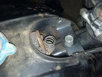
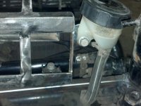
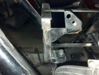
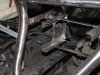
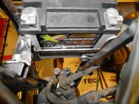
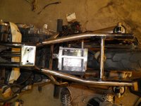
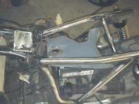
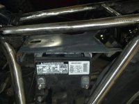
Ok, I wasnt happy with the rear M/C res. mounting. It needed to move forward and be much closer to "level" than it was. So tonight I redid that little bit and am much happier with the result. It tucks in better and will function better.
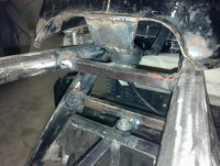
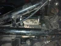
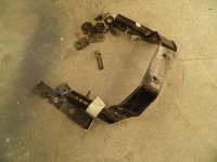
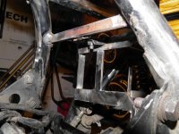
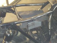
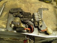
After that I moved to the mounting of the ignition coils. I didn't want to build a new bracket, so I thought I'd try using the old mounts but just flip them down instead of up. They were fouling on the bottom of the new tank, so something had to be done. In this configuration things will work out. I still have a little tweaking to do, but at least I know I dont have to finding room for them somewhere else.
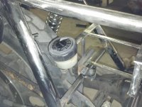
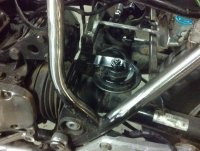
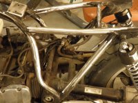
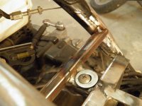
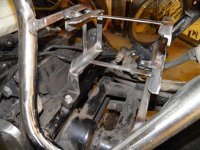
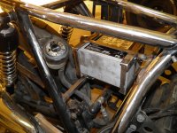
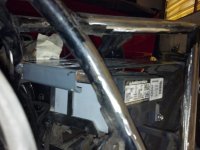
Next was the horn. I hate the look of most factory horns, so I like to tuck them deep in the bike where they can't be seen. In this case the bottom mounting bolt for the battery cage provided a great anchor point. Clearance t the top of the driveshaft tube/swingarm is ample, but I still may fab a new bracket to move the horn up a little bit for more clearance. It also places the horn close to the electrical system "center", keeping things simple and tidy where wiring is concerned.
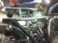
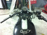
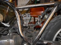
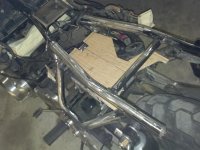
I also started to think about a speedometer. I think I will just use the stock unit. I had visions of selling the complete gauge cluster for a decent penny, but once I bought a new speedo, that would consume most of my profit from that sale. A bracket will need to be made to attache the speedo in the locations shown in the photo, using the ignition switch mounting bosses on the top triple. The switch will be getting replaced and/or relocated, so that mounting location will work out well.
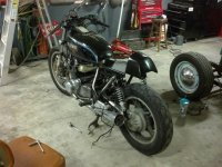
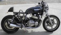
Things are slowly coming together, and I'm starting to get an idea of what the finished product is going to be here. Excited!
 

Attachments

  • rearmcresbrkt.jpg
    rearmcresbrkt.jpg
    44.9 KB · Views: 480
  • rearmcresbrkt1.jpg
    rearmcresbrkt1.jpg
    102.2 KB · Views: 223
  • new coil mounting.jpg
    new coil mounting.jpg
    52.2 KB · Views: 488
  • hornmounting.jpg
    hornmounting.jpg
    59.1 KB · Views: 476
cockpit and the overall shot from today
 

Attachments

  • cockpit.jpg
    cockpit.jpg
    52.7 KB · Views: 488
  • asof111113.jpg
    asof111113.jpg
    116.8 KB · Views: 221
wow, getting into the big steps now! i would kill to have a shop like that, I think I am going to have to find someone to cut/weld my seat pan... then I will probably make the seat myself with fiberglass. Looking good though!
 
Back
Top Bottom