
You are using an out of date browser. It may not display this or other websites correctly.
You should upgrade or use an alternative browser.
You should upgrade or use an alternative browser.
Down under, an idiot and a 400F
- Thread starter neevo
- Start date

crazypj
Split personality, I fake being smart
I tend to go too slow for the materials I use, too fast will burn tool tips
I rarely use more than 1500rpm. even on small diameters. As long as the tool is cutting and not rubbing you should get a reasonable finish.
Make sure your dead nuts on center height, above will cause tool to rub, below makes it dig in and material tries to 'roll over' the tool tip.
I've seen a lot of 'advice' about tool setting where they say to be slightly below center. few thousandths low is better than a few thou high but neither is as good as correct height
Some steels tend to tear, free cutting steels have lead added as a cutting lubricant.
If finish isn't very good, try a deeper cut with different feed rates. I tend not to use auto feed any more and do things by feel
Higher speed and 0.004"/rev feed should be OK from about 1/2" dia to 2" dia
There are formula's to work out rotational speed from diameter, I can't remember them though. I have most of my notes from 1974 somewhere although I know I gave a load of information away to a friend who bought a lathe (around 1980 : )
I rarely use more than 1500rpm. even on small diameters. As long as the tool is cutting and not rubbing you should get a reasonable finish.
Make sure your dead nuts on center height, above will cause tool to rub, below makes it dig in and material tries to 'roll over' the tool tip.
I've seen a lot of 'advice' about tool setting where they say to be slightly below center. few thousandths low is better than a few thou high but neither is as good as correct height
Some steels tend to tear, free cutting steels have lead added as a cutting lubricant.
If finish isn't very good, try a deeper cut with different feed rates. I tend not to use auto feed any more and do things by feel
Higher speed and 0.004"/rev feed should be OK from about 1/2" dia to 2" dia
There are formula's to work out rotational speed from diameter, I can't remember them though. I have most of my notes from 1974 somewhere although I know I gave a load of information away to a friend who bought a lathe (around 1980 :
)
neevo
Over 1,000 Posts
Cheers as always PJ. Just got a quick change tool post installed so getting tool height should be relatively easy.
Will have a little play around with it and see what I can make happen. I was roughing the radius so that's certainly an area I can improve. Will also try slowing the RPM's a little to see what that does.
Will have a little play around with it and see what I can make happen. I was roughing the radius so that's certainly an area I can improve. Will also try slowing the RPM's a little to see what that does.
crazypj
Split personality, I fake being smart
The major problem I've found with speed/feed calculators is they are designed for production facilities using flood coolant, the trade off between tool life and product output is the most important thing.
For hobby use, going slower and taking a little longer generally isn't a problem
If you were milling, it's a different story, cutters are designed to have a minimum tooth pressure or chips don't form properly.
Try putting a DTI on cross slide and measure tool deflection, sometimes you may have to go slightly high to compensate for less rigid toolpost
For hobby use, going slower and taking a little longer generally isn't a problem
If you were milling, it's a different story, cutters are designed to have a minimum tooth pressure or chips don't form properly.
Try putting a DTI on cross slide and measure tool deflection, sometimes you may have to go slightly high to compensate for less rigid toolpost
neevo
Over 1,000 Posts
I'm here in Vietnam (on holiday) planning the next addition to the bike: the exhaust system.
Spoken to my pipe bender and it looks like custom bent headers are definitely in the budget, even in stainless.
Also spoke to someone at Meg's about the bits I'll need for the merge and they were supremely helpful, fantastic response time and very accommodating for the help I required.
Looks like I have a choice on the header merge: weld on or slip on. I am leaning towards the slip on as I want the look of the springs etc, think this will add to the look of the bike:
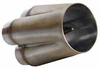
Rich at Meg's recommended a 1.75" outlet collector to match my 1.25" headers. He advised against the twin secondaries but I'm going to get the parts anyway and see how it goes, can always go with 1 muffler only if too much power is lost.
Once the headers are built I will look to have the custom secondaries bent and then get my buddy Darren at DnA Custom Cycles to whip up a pair of exhaust hangers.
Spoken to my pipe bender and it looks like custom bent headers are definitely in the budget, even in stainless.
Also spoke to someone at Meg's about the bits I'll need for the merge and they were supremely helpful, fantastic response time and very accommodating for the help I required.
Looks like I have a choice on the header merge: weld on or slip on. I am leaning towards the slip on as I want the look of the springs etc, think this will add to the look of the bike:
Rich at Meg's recommended a 1.75" outlet collector to match my 1.25" headers. He advised against the twin secondaries but I'm going to get the parts anyway and see how it goes, can always go with 1 muffler only if too much power is lost.
Once the headers are built I will look to have the custom secondaries bent and then get my buddy Darren at DnA Custom Cycles to whip up a pair of exhaust hangers.
neevo
Over 1,000 Posts
I also need some advice. The excel calculations for my 466 build recommend a 1" primary, assuming a small increase to assist with overcoming the bends I was going to use 1.25" stainless tube, anyone see any issues with this?
I can get a 1.25" 4-1 collector with a 1.5" outlet diameter from Megs but my plan to use a 2-1 (reversed) to get my twin pipes won't work as the largest inlet diameter I can find for a 1.5" outlet 2-1 is 1.25"
This wouldn't normally be a problem but the Yoshimuars I plan on using are super thick 2.25" inlet diameters. Therefore I am trying to get as close to possible to 1.75" to 2" on the 2x outputs of the merge so I have decent enough diameter to mount the Yoshimura's.
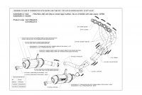
My only thought was to build the headers using the 4-1 above, then make the secondary's out of 2" tube and cut them and weld them together into a point and cut them at the correct diameter. eg:
Headers/4-1 merge/2" midpipes welded and cut to match merge/Yoshimura's:


The other option is to do a 4-2-1 using 2-1 collectors. Then I can get into the right output dimension although would be a bit big in the merge and could run into back pressure issues. eg:

I think I am starting to prefer this option.
I can get a 1.25" 4-1 collector with a 1.5" outlet diameter from Megs but my plan to use a 2-1 (reversed) to get my twin pipes won't work as the largest inlet diameter I can find for a 1.5" outlet 2-1 is 1.25"
This wouldn't normally be a problem but the Yoshimuars I plan on using are super thick 2.25" inlet diameters. Therefore I am trying to get as close to possible to 1.75" to 2" on the 2x outputs of the merge so I have decent enough diameter to mount the Yoshimura's.
My only thought was to build the headers using the 4-1 above, then make the secondary's out of 2" tube and cut them and weld them together into a point and cut them at the correct diameter. eg:
Headers/4-1 merge/2" midpipes welded and cut to match merge/Yoshimura's:
The other option is to do a 4-2-1 using 2-1 collectors. Then I can get into the right output dimension although would be a bit big in the merge and could run into back pressure issues. eg:
I think I am starting to prefer this option.

crazypj
Split personality, I fake being smart
The Kawasaki, et.al. is probably best bet. 1&4 to 'top' center and 2&3 to 'bottom' center into 2 collectors, collector outlet 1.7x diameter of one pipe into a third collector then reverse to get outlet size you want. 1" pipe is probably only 7/8" internal, 1-1/8" would be better to give 1" internal dia but 1-1/4" should be easier to get hold of.
You can angle cut section from pipes to get an 'oval' section 2:1 to act as collector, use a rusty fork tube as a mandrel to switch from oval to round
You want less than 2psi at the collectors, easy way to get anti-reversion is to fit pipe over the collector 'v' and have it act as a small expansion chamber
You can angle cut section from pipes to get an 'oval' section 2:1 to act as collector, use a rusty fork tube as a mandrel to switch from oval to round
You want less than 2psi at the collectors, easy way to get anti-reversion is to fit pipe over the collector 'v' and have it act as a small expansion chamber
neevo
Over 1,000 Posts
Yeah I was thinking 1-4 to top and 2-3 to bottom, certainly less buggering around with header placement that way to get the headers in the right location. Just means I have to remove headers to change oil filter. Not a huge problem, just make sure I have a supply of exhaust gaskets.
I am buying 2-1 collectors with bullet vanes from Meg's. What were you referring to in the last 2 sections?
I am buying 2-1 collectors with bullet vanes from Meg's. What were you referring to in the last 2 sections?
crazypj
Split personality, I fake being smart
Having headers set up like that means all the pipes can be made pretty close to same length
If the outlet of collector made from two pipes with a lengthwise angle cut, outlet can be 'correct' size with oversize pipe slid on. I should do a drawing , be much easier than trying to explain ;D
If the outlet of collector made from two pipes with a lengthwise angle cut, outlet can be 'correct' size with oversize pipe slid on. I should do a drawing , be much easier than trying to explain ;D

neevo
Over 1,000 Posts
Hence why I'm buying pre formed merges from Meg's 
They do a 1.25" to 1.5" which I'll use for connecting the headers and a 1.5" to 2" which I'll use to output to the secondaries.
2" pipe will be used for secondaries and I am going to see if I can join them together so they attach into the 2" outlet. Failing that I will grab another 2-1 and split the 1 into the 2 secondaries. Only concern with that is the total merge length as it would use 3 collectors at around 10" length.
Are the header lengths measured from exhaust port to the part where they all join (eg the part were they become 1)? Trying to gauge where my 25" header length should be measured to.
They do a 1.25" to 1.5" which I'll use for connecting the headers and a 1.5" to 2" which I'll use to output to the secondaries.
2" pipe will be used for secondaries and I am going to see if I can join them together so they attach into the 2" outlet. Failing that I will grab another 2-1 and split the 1 into the 2 secondaries. Only concern with that is the total merge length as it would use 3 collectors at around 10" length.
Are the header lengths measured from exhaust port to the part where they all join (eg the part were they become 1)? Trying to gauge where my 25" header length should be measured to.
neevo
Over 1,000 Posts
My electrics are all housed in the rear hump I made:

I plan on buying a newer rec/reg and mounting it on the battery box also on the left hand side of the bike:

Given the rec/reg can get warm as it dissipates excess voltage I am thinking some cooling may be in order to assist it in getting rid of this warmth. The battery box will help to a certain degree (through conduction) however I was thinking of adding a design feature to the rear hump that would act as a cooling vent:

Thinking of cutting something like this into the side of the seat:

Thoughts?
I assume it would get enough air circulating around the battery box to aid in cooling, plus would look cool. I assume any air that is forced in will find its way out through the subframe tray.

I plan on buying a newer rec/reg and mounting it on the battery box also on the left hand side of the bike:

Given the rec/reg can get warm as it dissipates excess voltage I am thinking some cooling may be in order to assist it in getting rid of this warmth. The battery box will help to a certain degree (through conduction) however I was thinking of adding a design feature to the rear hump that would act as a cooling vent:

Thinking of cutting something like this into the side of the seat:
Thoughts?
I assume it would get enough air circulating around the battery box to aid in cooling, plus would look cool. I assume any air that is forced in will find its way out through the subframe tray.

spotty
Vmax...why,yes i think i will
just a thought but you might be better off drawing air through rather thasn forcing it (and water) in, perhaps a hole something like that but with a rear facing scoop over it which as air goes past the opening will create a low pressure zone inside the rear hump which will then draw air up through the under-seat tray and the air passing the outside of the scoop will then draw this air (and heat) out into the air flow (if that makes sense)
another option might be louvres like the ones hot rodders have on the bonnets of their cars (these also always point backwards)
another option might be louvres like the ones hot rodders have on the bonnets of their cars (these also always point backwards)