
You are using an out of date browser. It may not display this or other websites correctly.
You should upgrade or use an alternative browser.
You should upgrade or use an alternative browser.
Down under, an idiot and a 400F
- Thread starter neevo
- Start date


neevo
Over 1,000 Posts
crazypj said:RMZ/KXF250 silencers

So cool. You're running headers around the side of the engine?
Don't suppose you've got a side view?
neevo
Over 1,000 Posts
On the first electrical system check I think I fried the RFID. Got a bit cocky with the wiring by running 2 feeds into one (one from the RFID and one from the LED switch) and I think some current went back up into the RFID and fried it.
So I decided to simplify the wiring a bit and wanted to go the extra step and stop any potential bleed back into the RFID. I thought I would step into something I've never done before: electronics!!!
So I bought some diodes and thought I would try out on the broken RFID first:

I have no idea which way it goes around so I put it on the tester:

I'm assuming the flow goes from the red to the black side (with the black stripe on it).
The white wire was the one I had joined with the LED switch:


I had a look at the board and tried to determine a good place to install the diode, it appears the pin on the left is the trigger feed, it was soldered to the right pin where the feed wire connector joins:

I thought the neatest way of doing it was to remove the pin on the left, solder in the diode wire and then solder it to the pin on the right. A little solder action and the pin slid right out:

Putting the diode in required a little finesse but it worked out in the end:

I'm happy with the test (although i want to solder the diode in a little neater) and will be doing the unbroken RFID in the next day or so
Can anyone confirm I've tested the diode correctly?
So I decided to simplify the wiring a bit and wanted to go the extra step and stop any potential bleed back into the RFID. I thought I would step into something I've never done before: electronics!!!
So I bought some diodes and thought I would try out on the broken RFID first:
I have no idea which way it goes around so I put it on the tester:
I'm assuming the flow goes from the red to the black side (with the black stripe on it).
The white wire was the one I had joined with the LED switch:
I had a look at the board and tried to determine a good place to install the diode, it appears the pin on the left is the trigger feed, it was soldered to the right pin where the feed wire connector joins:
I thought the neatest way of doing it was to remove the pin on the left, solder in the diode wire and then solder it to the pin on the right. A little solder action and the pin slid right out:
Putting the diode in required a little finesse but it worked out in the end:
I'm happy with the test (although i want to solder the diode in a little neater) and will be doing the unbroken RFID in the next day or so
Can anyone confirm I've tested the diode correctly?

MotorbikeBruno
Over 1,000 Posts
That's clean. Nice job man. I make custom medical cables for my day job, so I enjoy seeing the electrical aspects
Keep up the spectacular work man. 8)
Keep up the spectacular work man. 8)
neevo
Over 1,000 Posts
MotorbikeBruno said:That's clean. Nice job man. I make custom medical cables for my day job, so I enjoy seeing the electrical aspects
Keep up the spectacular work man. 8)
Cheers Bruno!!! Do you think I'm right with my assumption that the diode is in the right way (eg black stripe on the output side)?

rockcitycafe
I make things.
the stripe is the cathode side always
neevo
Over 1,000 Posts
Roc City Cafe said:the stripe is the cathode side always
And I'm assuming cathode is the exit (current out) side? Not too hot on the terminology.
rockcitycafe
I make things.
more or less, yes... anode side goes to positive, cathode to negative
neevo
Over 1,000 Posts
Roc City Cafe said:more or less, yes... anode side goes to positive, cathode to negative
Appreciate the help.
neevo
Over 1,000 Posts
Got the diode soldered into the working RFID, very pleased with the end result as its nice and neat. Tested it on the meter and it appears to all be working fine, time will tell when I get it wired into the bike and test it out for the first time:


Also been looking at exhaust systems. I've got my eye on some dual Yoshimura exhausts however the price is not cheap
You have to pay for quality though and these are nice and compact (14") with swish carbon end caps (bottom right version):

So I thought I would see if they would even work on the bike by making some analogues and testing some placements. So I grabbed some old water pipe and cut it to 14":

Rigging it up on the bike was tough,
But some string and a few bits of metal and I got somewhere:


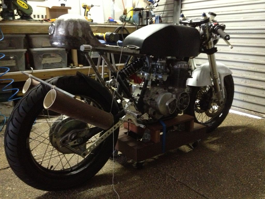
The placement is far from perfect but it was only a test of concept. I think I can make them work... just need to find a chunky amount of cash to afford them
Also been looking at exhaust systems. I've got my eye on some dual Yoshimura exhausts however the price is not cheap
You have to pay for quality though and these are nice and compact (14") with swish carbon end caps (bottom right version):
So I thought I would see if they would even work on the bike by making some analogues and testing some placements. So I grabbed some old water pipe and cut it to 14":
Rigging it up on the bike was tough,
But some string and a few bits of metal and I got somewhere:
The placement is far from perfect but it was only a test of concept. I think I can make them work... just need to find a chunky amount of cash to afford them

neevo
Over 1,000 Posts
So the front fender I got for the GSXR front end is going to go. It's too bulky and ugly looking and I don't want to cut it up and potentially ruin it, would rather sell it to someone that needs it as is:

I'm looking at alternatives to deliver the look I want and am curious which other bikes share the same forks as the 03 GSXR 750? I would assume a few as not all manufacturers are going to make their own forks! They are Showas I believe. Ideally I buy something that bolts on like a Ducati monster front fender:


Or if they won't fit I will buy the fender part off a Ducati Sport Classic and custom make a metal loop to attach it to the forks (not a cheap option though):

I'm looking at alternatives to deliver the look I want and am curious which other bikes share the same forks as the 03 GSXR 750? I would assume a few as not all manufacturers are going to make their own forks! They are Showas I believe. Ideally I buy something that bolts on like a Ducati monster front fender:
Or if they won't fit I will buy the fender part off a Ducati Sport Classic and custom make a metal loop to attach it to the forks (not a cheap option though):

ABCanuck
Coast to Coast
Not sure on mounting points but maybe take a peek at something like vf1000 front fender. It is kinda dwarfed by the square fairing but it is much lighter visually than the gsxr fairing. Here's a pic of mine.

Maybe still not what your looking for but just trying to throw out options.
Maybe still not what your looking for but just trying to throw out options.

ABCanuck
Coast to Coast
Oh geez, from that view, there is no question. Very, very nice. Strange how sometimes things that have more lines and angles can at the same time look sleeker, simpler, and in this case, bloody fast.
And Marc, I'm guessing you meant the alloy one neevo posted, not mine, correct?
And Marc, I'm guessing you meant the alloy one neevo posted, not mine, correct?

o1marc
Over 1,000 Posts
neevo said:$69? The one I have saved is $96, what's the link for yours?
360627833568
Seller has same fender listed twice, one for $69.99 and again for $99.95