
Sorry man, I don't understand this at allAlso, usually when you put a lead on each side of a switch, then hit the button, your number change or you get reistance numbers at all from OL or whatever your meter reads when there is zero resistance or unlimited resistance.
We noticed you are blocking ads. DO THE TON only works with community supporters. Most are active members of the site with small businesses. Please consider disabling your ad blocking tool and checking out the businesses that help keep our site up and free.
You are using an out of date browser. It may not display this or other websites correctly.
You should upgrade or use an alternative browser.
You should upgrade or use an alternative browser.
1982 CB750F...Better Devil
- Thread starter Jimbonaut
- Start date
Here is a video of me turning a switch on and off. Mine beeps, so ignore that.
Your ohm number doesn't matter. It just needs to read a number. Resistance is going to be different on different circuits with different thicknesses of wire and different wire alloys, switch alloys, etc. And I suppose the diode function may work, since a diode is basically an electronic check valve. If your meter reads OL when set to diode, but leads not touching, then reads 0 with leads touching, then it will work.
Well thank fuck for that. My El-Cheapo doesn't read OL, but has a number 1 without the leads touching. With them touching it reads 0.
If the diode setting is indeed ok to check for continuity, any idea why in the holy hell I haven't got any power to the headlight?
If the diode setting is indeed ok to check for continuity, any idea why in the holy hell I haven't got any power to the headlight?
Last edited:
"If you hook your meter to the yellow/red and black wire to your starter switch and push, it should beep." - meter reads 00.0 = continuity
"When you hook it to the blue/white and brown/black wires, it should beep when you're aren't pushing the switch." - meter reads 00.0 = continuity
"when all assembled and your key is on does your test light come on when touching the blue white wire? if so there is nothing wrong." - test light does come on
"You can also push the starter button and see if the light comes on touching the red yellow" - test light does come on
We've determined the starter switch and ignition switch works. That's what I gather here.
So far so good. Moving on to the hi/low beam switch -
"If you have power there correctly you need to move to the next switch and check the ins and outs. the hi/low. if you test the blue white going into that switch and there is power, something is off in the headlight switch" - test light does comes on
"If there is power and you check the white out for low beam and there is power there is a short in the wire to the headlight plug" - test light does not come on (when you say white out do you mean test the white wire where it is soldered to the headlight switch? That's where I tested it) so...
"If no power there is a problem with the contacts inside the switch" - I took that thing apart 5 times and cleaned it to within an inch of its life. Unless it's busted, the wires all look good, as do the contacts.
If I am reading this series of statements correctly, you have tested circuits between the head light switch and the plug for the headlight itself. You have no continuity between those switches, which tells me you have an issue with your headlight switch. Do you have a toggle switch laying around that you can put a couple of connectors on (or jumpers made from two alligator clips and a length of wire) to bypass the headlight switch and see if it works?
I checked continuity from the blue wire at the headlight switch to the other end at the headlight plug - good continuity
I checked continuity from the white wire at the headlight switch to the other end at the headlight plug - good continuity
I checked continuity from the green wire at the headlight plug to the other end where it grounds to the coils - good continuity
This confuses me. Why is it grounded to the coils? Is this ground a confirmed ground to frame and/or battery negative?
"If you hook your meter to the yellow/red and black wire to your starter switch and push, it should beep." - meter reads 00.0 = continuity
"When you hook it to the blue/white and brown/black wires, it should beep when you're aren't pushing the switch." - meter reads 00.0 = continuity
"when all assembled and your key is on does your test light come on when touching the blue white wire? if so there is nothing wrong." - test light does come on
"You can also push the starter button and see if the light comes on touching the red yellow" - test light does come on
We've determined the starter switch and ignition switch works. That's what I gather here.
So far so good. Moving on to the hi/low beam switch -
"If you have power there correctly you need to move to the next switch and check the ins and outs. the hi/low. if you test the blue white going into that switch and there is power, something is off in the headlight switch" - test light doescomes on
"If there is power and you check the white out for low beam and there is power there is a short in the wire to the headlight plug" - test light does not come on (when you say white out do you mean test the white wire where it is soldered to the headlight switch? That's where I tested it) so...
"If no power there is a problem with the contacts inside the switch" - I took that thing apart 5 times and cleaned it to within an inch of its life. Unless it's busted, the wires all look good, as do the contacts.
If I am reading this series of statements correctly, you have tested circuits between the head light switch and the plug for the headlight itself. You have no continuity between those switches, which tells me you have an issue with your headlight switch. Do you have a toggle switch laying around that you can put a couple of connectors on (or jumpers made from two alligator clips and a length of wire) to bypass the headlight switch and see if it works? nope, sadly not.
I checked continuity from the blue wire at the headlight switch to the other end at the headlight plug - good continuity
I checked continuity from the white wire at the headlight switch to the other end at the headlight plug - good continuity
I checked continuity from the green wire at the headlight plug to the other end where it grounds to the coils - good continuity
This confuses me. Why is it grounded to the coils? Is this ground a confirmed ground to frame and/or battery negative? the harness is grounded to the coils - there's a green wire that comes out of the harness and is bolted to the frame with the coils. I could be missing something, in fact fuck I probably am. There is a ground strap from the negative terminal of the battery to the engine mounting bolt as well. How do I check the ground is good? Christ I feel like a real idiot. Electricity man, fuck.
Haha. I procrastinate finishing builds when I get to the wiring part, so I get it. The same process for testing your switches and circuits also applies to grounds. All grounds should have continuity between the ground wire and the negative terminal on your battery.
Another option to bypass your headlight switch would be to make some jumpers that go from the wire before the switch to the wire after the switch. In other words, the blue white wire feeds power to the switch. Hook a jumper from that wire to either the blue or white wire on the other side of the switch or directly to the blue or white prong on the headlight itself.
Another option to bypass your headlight switch would be to make some jumpers that go from the wire before the switch to the wire after the switch. In other words, the blue white wire feeds power to the switch. Hook a jumper from that wire to either the blue or white wire on the other side of the switch or directly to the blue or white prong on the headlight itself.
Maritime
Over 10,000 Posts
Edit, my bad I got the pics messed up. Does the big plate = Blue White and does it have 12V?
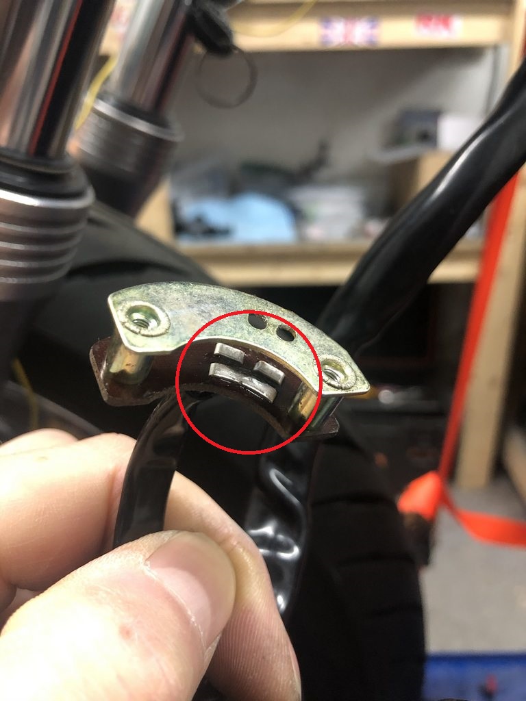
the white slide connects the Blue White to the white in low and the blue in high and if there is no juice it won't work. also the big plate looks bent and twisted and may not be making proper contact.
the white slide connects the Blue White to the white in low and the blue in high and if there is no juice it won't work. also the big plate looks bent and twisted and may not be making proper contact.
Maritime
Over 10,000 Posts
The yellow line. that plate needs to be level and straight to the other two and it looks crushed. The plate on the white slide that goes inside rides on the those to make the circuit. there are 2 ridges on the white slide that also need to be good and clean, filed bright. You can use a small flat head screw driver to lift and fix the plate, carefully not to break the solder joint under it.

This plate has a ridge on either end that if worn off may need a bit of solder to bring back contact with the other plates.
This plate has a ridge on either end that if worn off may need a bit of solder to bring back contact with the other plates.
Thanks - I'll pull the bugger apart and check those contacts again, make sure they're in good shape and filed clean. I'll also check the grounds too. One way or another I'm going to get this damn headlight illuminated.
Is it possible the new indicators that double up as running lights are screwing up the whole shebang?
Is it possible the new indicators that double up as running lights are screwing up the whole shebang?
Maritime
Over 10,000 Posts
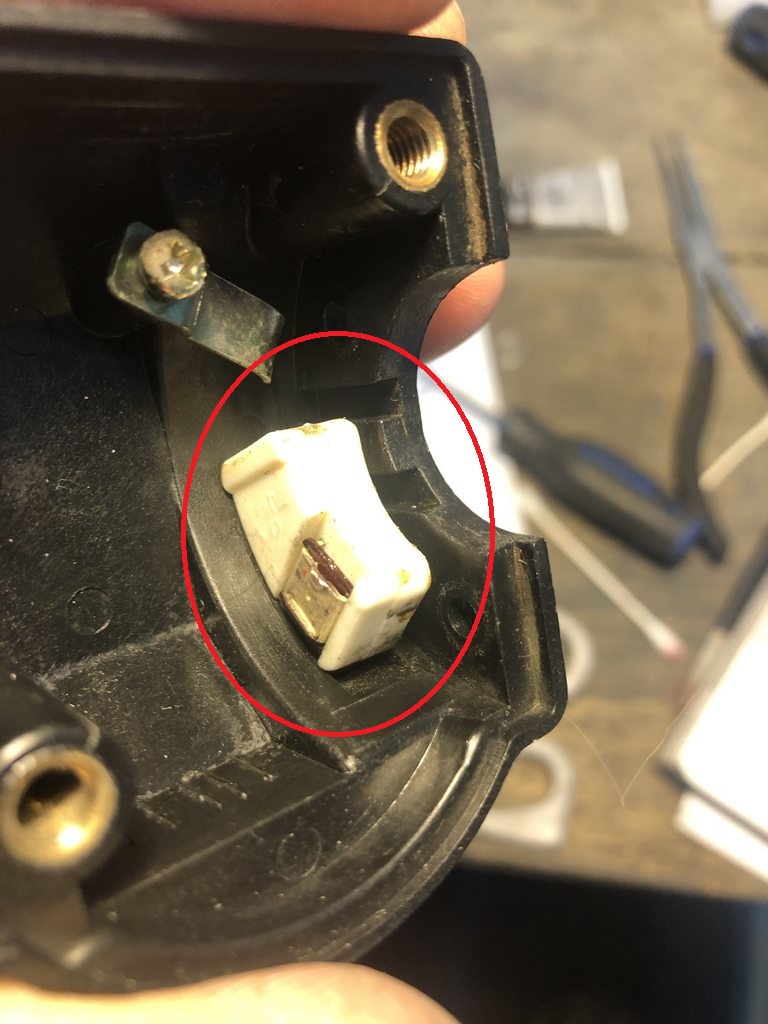
nope, they run off different circuits. Your switch looks like the culprit to me. make sure the long plate is level with the 2 split ones beside it. and that the tangs on the square make good contact to it and the split plates.

the little square in the white slide is the red square in the drawing. It connects the + from the B/W to the low or high depending on where you slide the switch. you need a good solid clean contact on these or they short out.
the little square in the white slide is the red square in the drawing. It connects the + from the B/W to the low or high depending on where you slide the switch. you need a good solid clean contact on these or they short out.
That makes sense Mike, thanks for the explanation. I'm a visual person, so that drawing really helps me make sense of all this. Although I feel a little like Sisyphus pushing that fucking great boulder up a mountain only to get to to the top and watch the thing roll down the other side and then have to start all over again, I'm also learning how the harness actually works. I'm sure it's like most other Dark Sciences - they're dark until someone turns the light on.
I Shall Pevail.
I Shall Pevail.
Maritime
Over 10,000 Posts
yep it takes me some figuring for sure when I need to find something like this. be easier if I could just pop over and have a beer with you while we traced the circuits involved till we got the light on LOL. If you follow the diagram from the + in to ground you'll see all the places there is a connection that needs to work, go from the first to the last and find the one the test light stops at and sort out why. Then Hi Low switch is that spot right now.
Jesus , Joseph and Mary eating marshmallows. Finally got the bastard illuminated. Yeah I whooped.
Figured Irk meant something like this when he talked about jumpers. I used a length of wire wrapped around the contacts and sure enough finally tricked some power to the headlight socket -


That alone was a milestone. Finally, some headway. So I took the hi/low switch apart - again - and added a small amount of solder (good call Maritime) to the contact pad. Reassembled and oh yes oh yes oh yay -

Light. And a shitload of it. This new led headlight'll definitely light the way and then some. May even give Maritime's gl a run for it's money in the illumination department")
Indicators also hooked up and working -

They have a cool flowing thing going on when the indicators are lit. Still need the right flasher relay but good enough for the time being. Spliced and soldered the tach to the speedo wiring -

and recycled the OEM gauge cluster plug for a clean fit into the harness. Dials work (finally) -


Front end starting to come together. I really like the headlight brackets I bought from @speedmotoco - they needed a little customizing to fit the indicators in a position that worked for me but damn they look sharp.

Shingles may be kicking in like a martha focker but whatever. A good day. Thanks gents once again. Onwards.
Figured Irk meant something like this when he talked about jumpers. I used a length of wire wrapped around the contacts and sure enough finally tricked some power to the headlight socket -
That alone was a milestone. Finally, some headway. So I took the hi/low switch apart - again - and added a small amount of solder (good call Maritime) to the contact pad. Reassembled and oh yes oh yes oh yay -
Light. And a shitload of it. This new led headlight'll definitely light the way and then some. May even give Maritime's gl a run for it's money in the illumination department
Indicators also hooked up and working -
They have a cool flowing thing going on when the indicators are lit. Still need the right flasher relay but good enough for the time being. Spliced and soldered the tach to the speedo wiring -
and recycled the OEM gauge cluster plug for a clean fit into the harness. Dials work (finally) -
Front end starting to come together. I really like the headlight brackets I bought from @speedmotoco - they needed a little customizing to fit the indicators in a position that worked for me but damn they look sharp.
Shingles may be kicking in like a martha focker but whatever. A good day. Thanks gents once again. Onwards.
Last edited:


