Follow along with the video below to see how to install our site as a web app on your home screen.
Note: This feature currently requires accessing the site using the built-in Safari browser.
We noticed you are blocking ads. DO THE TON only works with community supporters. Most are active members of the site with small businesses. Please consider disabling your ad blocking tool and checking out the businesses that help keep our site up and free.
Just a quick update. The two part foam is ordered for the seat and tank plug build up and according to tracking information will be delivered today. If all goes well over the next few days I should have photos uploaded of the freshly created plugs. Wish me luck and enjoy your turkey day.
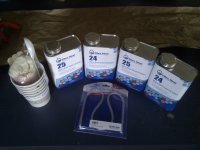
Oh yeah work weeks over! 5 days off and 4 to really get some work done on the bike. Well as promised the two part foam delivered and I will be very busy with the seat/cowl and tank plug buildups during this time. So the items I purchased in this photo: Mixing kit (cups,gloves, tablespoon, measuring cup), 24 inch flexible ruler (with standard and metric measures), and 4.8lbs of two part polyurethane foam. Tomorrow is going to be like Christmas when I get up. Let the composite experiment begin. lol
So here we have the begining of the composite work. This process will be done in stages. This is stage 1 plug construction. So I decided to build my composites up by starting with a plug, making a mold from the plug, and then the final part from the mold. This is done so should I have any of the the parts get damaged I can make an exact replica. As a side note any one interested in fiberglassing check out "gasserglass" channel on you tube. The guy has been doing this type work for 30+ years and makes some really good videos for instruction. So I ended up working on this on thanksgiving after all. lol. I knew I would. This series of pictures will show my form for the seat. The expanding foam after about two minutes and going all the way through to the rough plug shape. I will give details that are important in the necessary photo sets.
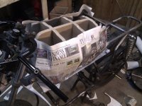
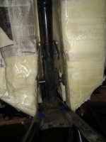
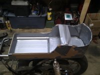
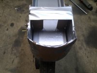
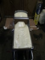
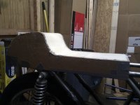
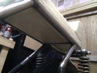
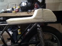
In this set I am showing my form construction for the seat and tail. The walls were made vertical and the side profile was set up for the basic shape I wanted. This provides me with the general shape I needed. I will trim and sand on it to get the final shape desired then prepare it for the mold work. On a side not you will notice I lined the entire form with duct tape. This was done to keep the foam from sticking to the cardboard. I wasnt sure if it would work but actuall worked great. Part of the duct tape shiny covering came off on the foam but overall it was a success. Seeing how it was on areas that will be sanded it was not a big deal. The form drops bellow the frame rails on the front section and above them on the rear. When you see the final it will be the result of that setup. The reason I have done this is my seat is also partially my coolant storage tank for the liquid to air intercooler. Remember Im hiding everything I can. lol.
Let the upload begin.
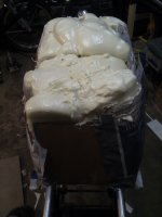
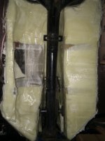
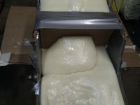
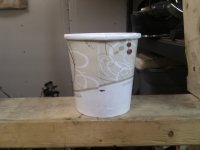
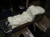
So with the form set and ready it was time to mix the foam and begin the pour. I used the #24/#25 Polyurethane foam from Fibreglast.com shown in the earlier photos. This foam mixes at a 1:1 ratio and is super tough once it has hardened. All of this is my first attempt at any composite work so you are learning with me as I go. The first photo is Foam A and it shows the cup size I mixed in. The black line on the cup reflects how much was put in each cup before combining the two part. Once combined I made two pours of this amount with the first in the front section of the form. The second in the back section. The remaining photos in this post reflect the result of these two after expansion. I did not measure volume and calculate need I just guessed. They did come up short in some areas but I would rather add more than have to much waste. Of course if your going to do it by the book follow the directions and calculate your volumes. I may do that latter but I am happy with my results.
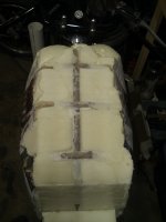
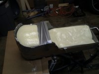
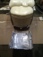
So after that hardened enough to do some finishing pours I mixed about half the amount shown in the previous cup and and finished with two additional pours of this amount. These photos reflect that end result. On the last photo I removed the tail part of the form so you can see how it did not stick. At this point I have hardly used my liquid foam. My guess would be 1/3-1/2 of one set of the 2.4lb foam containers. Total cure time on these per the label is 20 minutes. One note you will notice an indentation on the vertical angle of the seat back. I had to put a piece of card board across that to keep it from expanding out instead of up. I had thought about that when I was building the form and forgot to install it before the pour. I just held a piece across there long enough for it to rise and gel. I pulled it before it hardened.
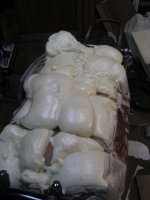
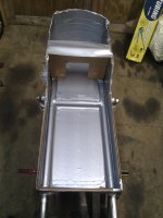
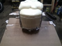
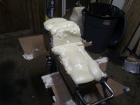
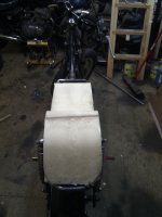
So here I have my form with the foam all cured and the initial trim performed. One thing to note is my rear angle was alittle sharper than I expected and end up cutting it short. You can see it in Foam 12 photo. However the nice thing with working with this material is I can go back and add some more in that area to get my design back where I want it. I used a hack saw to trim this being careful to not cut into the cardboard guide. You can work with this material with just about any type of cutting/sanding material you want.
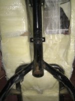
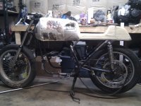
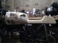
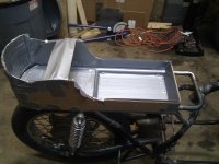
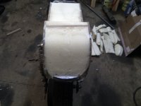
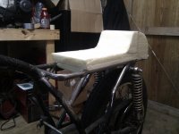
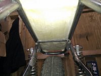
So here I have the form removed with the plug sitting on the frame. So far it is comming along very well and I am happy with the results. One more photo set after this post.
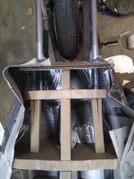
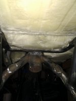
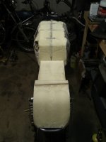
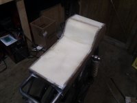
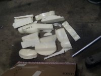
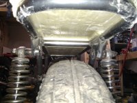
Last set of photos to bring you up to the current state of the project. These are some close ups of the underside. Photos Foam 17,18 are looking aft from the engine area and Foam 20 is the underside looking forward from the rear. Foam 9 photo is the scrap I had left over. I have not begun any detail shaping yet to this. This is just the rough outline. I will be making the tank plug today and once both of them are in there rough form I will begin the final shaping. This was done so I could ensure the best fit between the two and the shaping can be done to get the best match. Hope this has been helpful so far. Stay tuned the tank will be done next.... Almost forgot to mention. I was saying this foam is tough. Even though you can sand and cut it easily the density actuall permits me to sit on it in this form with out deforming it or any damage. Obviously dont bounce on it or anything crazy. I weigh 164 lbs so it is quite sturdy.
deepwaterimports,
Thanks. I wish I could take credit for the idea but being being engineering minded I over research things before I do them. This method was brought up in one of fibreglast's how to videos and I just adapted it.
roman_dog,
Appreciate the compliment. The photos for the rough tank are coming after this post.
phat13,
I absolutely agree. This foam is great to work with and with my vivid imagination I just have to make sure to not get carried away. lol. Can't wait to start on my GPZ1500 turbo bagger after this one is complete. Have some really good ideas from this experience.
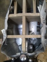
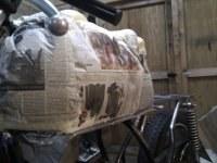
All right guys/gals here is the result so far of 12 hours in my shop yesterday. I want to apologize for I wasnt as thorough with the photos on this section. I was wrapped up in my head. lol. So lets begin with a description of what I did. I knew I really liked the general shape of my GPZ1100 tank and it seemed to match up with a cafe bike so I used it for my base design. The tank is way to long and wide for this bike but some of the general curves and shapes I liked. Using rough approximations I made a 3 section mdf form with a centralized spine. This is the portion that took most of the day. Had to be just right for this is what will guide the shaping of the form. Once this was complete I removed it and installed the cardboard and duct tape block offs around the backbone of the frame. This would provide my tunnel void for the tank. I followed this with a flat cardboard duct tape covered section bellow the backbone and even with the bottom edge of the rear frame rails. Joined it to my back bone void so that it would act as the bottom of the tank and provide a support when I poured the foam. Then I stapled some newspaper (tip in the fiberglast videos) to the intercooler cut out in the wood skeleton, setting this over my backbone and on top of the base. Once this was complete I stuffed balled up news paper in the area where the intercooler would be and balled up some news paper to create an area for the inlet and outlet piping to go. This was all duct taped over to give me a pretty good cut out for the intercooler and to keep the foam from sticking to the newspaper. Using two small pieces of cardboard, that matched the factories front rubber mount diameters, I duct taped all of this to my back bone cover. I made sure to bring it all the way to the front edge so the tank would have the ability to slide on and bolt in the back. Finally I attached another duct tape covered section of cardboard to the rear of the wooden skeleton. Once this close off section was done I went around the entire form with newspaper taped and the base about 1/2 inch out from the wooden form and stapled it up approximately 3/4 of the way up the skeleton. BIG NOTE: Leave yours loose if you do this. It allows the foam to expand past the skeleton and you have enough to shape. I did this and it worked out great. The newspaper will of course stick to your foam but if you left it to have excess it will go away when you shape it. I probably could of used a trash bag for this portion but I had my girlfriends wall street journals everywhere. Reuse, Recycle, LOL. So here we have the pictures of the form all set for the pour. Enjoy.
You'll notice in the previous pictures on the right side in the bottom the intercooler void. You will also realize that the wood form is part of the plug. This works great to provide you with you general shaping outline. Just rough shape to the wood form but not past it and instant basic shape. So next we have the foam poured in and cured up. Yes it looks like a mess but looks are deceiving. lol.
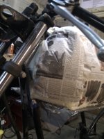
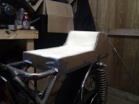
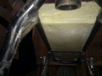
Ok now that we have the foam all cured up its time to begin pulling the form away. I can not say enough how much I love the duct tape. It makes this process so easy. Im sure there are better ways to do it but it works so why chance it. With these you can see the basic form removed. Youll see in tank foam 9 that I have the seat installed and the picture is taken from the rear looking forward. Nice close fit in this area. It will end up having about a 1/8-1/4 gap between them so the wont rub. The underside also shows the intercooler cut out. Its the area with the short news paper attached. The rear side of the tank you can see the wood form faintly in the foam. The tank will actually be shaped to that level.
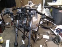
All right here is the last series of photos for this portion. I only did some very, very rough cutting on the top to give a general idea. After 12 hours of work on this yesterday I was tired. Todays work will consist of getting the tank rough shape down to a more manageable size. (A couple notes on the rough shape. The tank seems huge in these photos and on the bike but remember this is expanded out past the skeleton. Also on the rear view I will be bringing the knee "dents" in even with the seat so this area is wider than the final shape.) Once I have that done the plugs can start there fine shaping and preparation for mold construction. I have also included the seat in these to give a good idea of how it all ties together. So until the next installment enjoy your builds/bikes.
Interesting art project.
But you might want to get rid of that goose that shit on your bike.
Seriously, pins and plates and road rash scars are not all that much fun.
Been there done that, different cause,same effect.
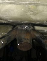
I hope the rest of your welds don't look like that.
If your uncomfortable welding out of position( overhead), flip it over.
The 'bead' looks a little cold,turn up your amps.
I hope you take this as some constructive criticism from a person with a 15 years experience as certified welder in the high pressure steam boiler field.
Nebr_Rex,
Yes I value constructive criticism especially from an experienced individual in any field. No the rest of the welds do not look like that and the amperage was tested on a second piece of like metal so I could cut it apart and verify penetration. This particular weld I myself do not like and haven't went back and fixed it. (after it was welded found my welder was on a different setting then the others.) I started on the composite work once the basic portion of the frame was complete due to these items taking the longest to perform. I still have alot of welding, de-tabbing etc... to perform. Thank you for your input.
This site uses cookies to help personalise content, tailor your experience and to keep you logged in if you register.
By continuing to use this site, you are consenting to our use of cookies.

")