Follow along with the video below to see how to install our site as a web app on your home screen.
Note: This feature currently requires accessing the site using the built-in Safari browser.
We noticed you are blocking ads. DO THE TON only works with community supporters. Most are active members of the site with small businesses. Please consider disabling your ad blocking tool and checking out the businesses that help keep our site up and free.
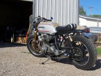
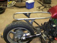
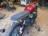
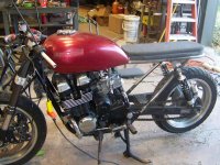
The tire has more clearance than my other bike, which has basically the same rear suspension setup. I'll probably do something similar for the license plate, running it at an angle. I have plans for a different tail light though. Here's a pic of the Hooptie to give you an idea.
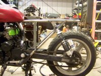
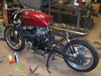
Got to work on the rear shock mounts today. It was a little tricky getting everything to line up right, but in the end it came out great. It's nice to have the bike back at a point where I can roll it around again too. Now I just gotta finish mounting the tank, do some electrical work, and build a seat. then I gotta do all the final work on the front end as well.
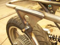
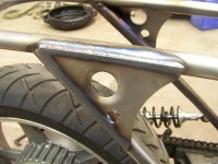
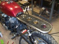
Spent a little time making the rear tank mounts and frame gusset today. I thought about modifying the tank and adding a mounting bracket more like the Honda ones, but after thinking about it I decided it'd be better to just use what was already there. The Kawi tank uses a pin on the bottom to locate the tank and another pin/hook thingie to hold it down. I fabbed up a little stand for the locating pin, then drew up the frame gusset with an extra tab to bolt on a removable mount for the hold down. For cushioning I actually used the 2 rubber grommets from the original honda tank that the side panels snapped into. Worked out pretty nice, and holds everything quite securely.
I second the kudos on your mad fab and welding skills. What was the purpose of the upside down shocks and do you plan on running them that way? I don't understand why, if you have tube bending capability, you didn't bend the tube in one piece instead of all the weld joints and plugs?
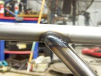
I built the seat hoop in 3 pieces for a couple reasons. First of all, there's a limitation on how close to each other you can make 2 bends, the tubing simply wont fit into the bender that close to a bend. Also you have to figure out exactly how far apart to make the bends before making them. In a situation like this 1/8" makes a big difference in how everything lines up, and to be honest I didn't know exactly how it was gonna fit before building it. Doing it in pieces allows you a lot more room to grind and adjust and fine tune.
As for the shocks, yes I do intend to run them upside down. With the piggyback reservoir there is a divider between the oil and the gas, so you'll never have a problem with the piston coming out of the oil and losing damping. In other words the shock doesn't really care which way is up. It's just compressing and rebounding. If you had an emulsion style shock without that divider it'd be a different story. In this case the shocks simply fit better mounted that way.
I am going to make a swing arm brace this week and your concerns on the bender will play into my decision to make it in one piece or not, it makes sense. I am doing 3" bends with only 2" of straight between them, I may not be able to do it. I agree with your thoughts on the shocks, I just wanted to hear from you why.
Some benders can get closer than others, mine requires about 4" or so. Also depending on the part you're bending if you know how much tube length the bend consumes you can start from the opposite end and bend towards the center, doing it that way is a lot more tricky though.
I need 2 3" bends with 2" in between to make it a total of 8" wide, then a bend 12" away at a 90* (or less)upward bend on each end of the "U". The guy I may have do it won't be back from Disney World until next week. He bends handlebars so I think this should be a cake walk for him.
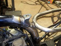
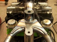
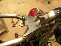
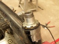
A couple last updates before I head off for vacation. I decided to finally finish up on the front end today after packing for my trip. First up was finalizing the steerer tube. Just like my last bike I pressed out the stock Kawasaki steerer which is a lot bigger than the Honda. I then salvaged the stock Honda piece by grinding the welds off the bottom of the lower crown, then pressing it out. To make the little peg fit the big hole I machined a sleeve with outside dimensions to match the Kawi, and inside diameter to press the honda into. I didn't remember to take a picture of the sleeve, but it's basically just a carefully sized tube with a step in the end so that it cant slide all the way through the lower crown.
After pressing all the pieces together all I had to do was weld the bottom of the honda steerer to the sleeve and assemble. For the top crown I simply machined a little aluminum sleeve to fill the space between the tube and the hole in the crown.
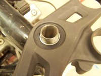
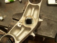
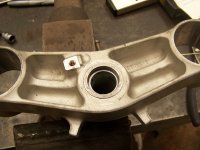
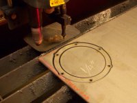
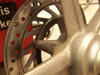
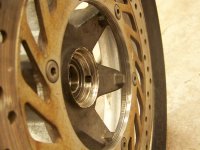
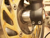
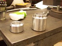
Now that the forks were firmly attached I moved onto the wheel. I think I mentioned before that the rotor didn't line up properly with the caliper, or that the wheel wasn't centered, depending on how you look at it. I needed to move the rotor out 1/4" to get things right, so I made a spacer. In case anyone was wondering how I cut out all these complex parts so accurately....I cheat. CNC makes things a lot easier.
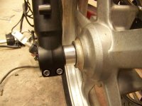
Last on todays list was to make the actual spacers for the front wheel. Not a terribly interesting or difficult process, but a bit tedious to get the dimensions right since It's difficult to get any measuring tools in there. It's done now though.
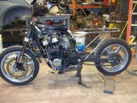
And now the bike looks just like it did yesterday, except that the front end is actually straight and firmly attached.
Well this thing has kinda been on the back burner for a while, but I'm trying to get moving on it again. I figure I'm paying for insurance, I should at least get it running.
First thing I did was to finally cut out the seat pan. Simple piece of sheetmetal with some speed holes to add lightness. I then glued a couple layers of foam together and started cutting and shaping til I got it where I wanted it. The foam is now out getting upholstered.
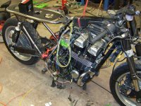
And now for the tedious part. This thing has a ton of excess wiring in it because they originally located so much of the electrical junk in the tail. I wanna hide it all under the tank so I got to work picking everything apart and shortening it one wire at a time. The back half is pretty much done now, next step will be to do the same to all the wiring going to the gauges, switches, etc.
Lookin good. I think my next build will have a fairing like that. These bikes are really cheap at the moment, which is why I got this one. I kinda like getting something a bit newer and less beat down, but it does require quite a bit more chopping to the frame. Thankfully that's something I'm quite comfortable with.
Talked to the upholstery place today and they have my seat ready. Cant wait to see how it came out!
This site uses cookies to help personalise content, tailor your experience and to keep you logged in if you register.
By continuing to use this site, you are consenting to our use of cookies.