Project CB690 (KTM 690 engine in a CB550f frame)

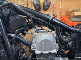
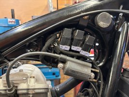
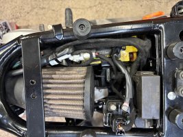
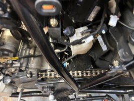
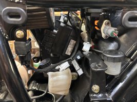
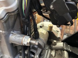
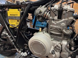
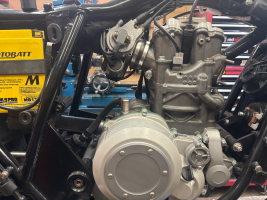
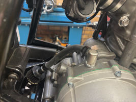
General tidy up and fussing with harness continues. Almost done.
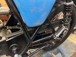
 

Attachments

  • IMG_2100.jpg
    IMG_2100.jpg
    1.7 MB · Views: 104
  • IMG_2107.jpg
    IMG_2107.jpg
    1.7 MB · Views: 80
  • IMG_2106.jpg
    IMG_2106.jpg
    1.6 MB · Views: 67
  • IMG_2105.jpg
    IMG_2105.jpg
    1.7 MB · Views: 71
  • IMG_2104.jpg
    IMG_2104.jpg
    1.7 MB · Views: 68
  • IMG_2103.jpg
    IMG_2103.jpg
    1.9 MB · Views: 68
  • IMG_2102.jpg
    IMG_2102.jpg
    1.3 MB · Views: 65
  • IMG_2101.jpg
    IMG_2101.jpg
    1.4 MB · Views: 67
I have a plan to revise the engine breather port. Right now it just sticks straight up in the air, and the hose has to do a beg bend before it can go down to the breather filter located down by the centre stand. The plan is to use an M16 brass hose barb, lathe off the barb, and make a cap from 20mm OD brass rod. Then to lathe the threaded end off of another barb fitting, mill a corresponding hole in the cap, and silver solder the whole thing together. Should be a fun lathe/mill/ soldering project. I already did some silver soldering on the brake line and it came out great, so I'm looking forward to this one. Parts are on order.
 

Attachments

  • image.png
    image.png
    98.3 KB · Views: 43
  • image-4.png
    image-4.png
    21 KB · Views: 41
  • image-3.png
    image-3.png
    42.3 KB · Views: 40
  • image-2.png
    image-2.png
    48.9 KB · Views: 43
  • Screenshot 2024-12-23 at 16.40.00.png
    Screenshot 2024-12-23 at 16.40.00.png
    2 MB · Views: 51
The brass rod arrived before Xmas so I spent some time on Boxing Day making the cover part of the breather assembly. When the other bits arrive I'll mill the side hole and solder it all up.
 

Attachments

  • IMG_2198.jpg
    IMG_2198.jpg
    1.3 MB · Views: 49
  • IMG_2197.jpg
    IMG_2197.jpg
    902.5 KB · Views: 46
  • IMG_2196.jpg
    IMG_2196.jpg
    1 MB · Views: 49
  • IMG_2192.jpg
    IMG_2192.jpg
    1.2 MB · Views: 49
  • IMG_2173.jpg
    IMG_2173.jpg
    1.7 MB · Views: 52
Quick one, I made a custom length starter cable. Because it goes straight up, it needed a straight boot. I bought a new boot for a Coax SMA cable, it worked great.
 

Attachments

  • IMG_2201.jpg
    IMG_2201.jpg
    1.3 MB · Views: 51
Making a new chain guard. I decided the aluminium one looked too home made. I bought several cheap chain guards from China and tried them out, one of them fit pretty well but did need to be extended. So I chopped up a few and bolted them together, you can't really see the seam under the sidecover. I did some plastic welding trials by heating up an implement with a torch and melting the two pieces, that worked well and I'll do it in addition to the bolts. These things are NAFF. Really cheap quality. But with some finessing and paint they look good, and will disappear when it's all together.
 

Attachments

  • IMG_2199.jpg
    IMG_2199.jpg
    1.6 MB · Views: 52
  • IMG_2200.jpg
    IMG_2200.jpg
    1.8 MB · Views: 50
  • IMG_2202.jpg
    IMG_2202.jpg
    1.6 MB · Views: 53
I received the parts for the breather and started modding them. Cut down both of the M16 barbs as shown, and fit them to the already made cap. Mocked up on the engine.
 

Attachments

  • IMG_2214.jpg
    IMG_2214.jpg
    2 MB · Views: 47
  • IMG_2213.jpg
    IMG_2213.jpg
    1.1 MB · Views: 45
  • IMG_2212.jpg
    IMG_2212.jpg
    1.8 MB · Views: 44
  • IMG_2211.jpg
    IMG_2211.jpg
    1.8 MB · Views: 47
  • IMG_2210.jpg
    IMG_2210.jpg
    1.8 MB · Views: 45
  • IMG_2208.jpg
    IMG_2208.jpg
    1.7 MB · Views: 47
Made a test piece to try out cutting the hole in the side of the cap. I used the mill attachment on the Clarke lathe, using successively larger drill bits then a boring bar to get to final dimension. Last picture shows the test parts assembled.
 

Attachments

  • IMG_2218.jpg
    IMG_2218.jpg
    1.6 MB · Views: 45
  • IMG_2217.jpg
    IMG_2217.jpg
    1.5 MB · Views: 46
  • IMG_2216.jpg
    IMG_2216.jpg
    1.3 MB · Views: 46
For real now, bored the hole in the cap. Very nice fit, very happy with that. Parts mocked up and looking almost exactly like the CAD model. I don't LOVE the breather hose in that location, but it has to go somewhere, and it does look better than the previous arrangement.
 

Attachments

  • IMG_2228.jpg
    IMG_2228.jpg
    1.4 MB · Views: 44
  • IMG_2227.jpg
    IMG_2227.jpg
    1.5 MB · Views: 47
  • IMG_2226.jpg
    IMG_2226.jpg
    1.4 MB · Views: 45
  • IMG_2225.jpg
    IMG_2225.jpg
    1.6 MB · Views: 49
  • IMG_2224.jpg
    IMG_2224.jpg
    1.4 MB · Views: 48
  • IMG_2223.jpg
    IMG_2223.jpg
    1.4 MB · Views: 46
  • IMG_2222.jpg
    IMG_2222.jpg
    1.4 MB · Views: 47
  • IMG_2221.jpg
    IMG_2221.jpg
    1.3 MB · Views: 46
I silver soldered the test parts together. Wire brushing didn't work too well, but after a quick bead blast and some scotch bright it looks great. It looks really, really good. Very happy with how that turned out. I will bring this test piece to the chemist at work and have her nickel plate it, if it looks good I'll have the final part nickel plated as well. If not I'll paint it black.
Tomorrow the final part will get soldered up.
 

Attachments

  • IMG_2234.jpg
    IMG_2234.jpg
    1.6 MB · Views: 55
  • IMG_2233.jpg
    IMG_2233.jpg
    2 MB · Views: 52
  • IMG_2229.jpg
    IMG_2229.jpg
    990 KB · Views: 57
Mocked up the breather on the engine and indexed the threads to the outlet. Then silver soldered both bits on at the same time. Bead blasted it, more scotch bright, and wham-o, all done. Except for the final breather filter mounting and nickel plating.
 

Attachments

  • IMG_2235.jpg
    IMG_2235.jpg
    1.2 MB · Views: 57
  • IMG_2236.jpg
    IMG_2236.jpg
    1.1 MB · Views: 56
  • IMG_2237.jpg
    IMG_2237.jpg
    1.5 MB · Views: 47
  • IMG_2238.jpg
    IMG_2238.jpg
    1.2 MB · Views: 51
The vent cap has been nickel plated and installed. Despite indexing the threads, when it was fully tightened I wasn't happy with the outlet position so I quickly made a 2mm thick Aluminium washer to adjust the rotation. Very, very happy with how it came out.
 

Attachments

  • IMG_2366.png
    IMG_2366.png
    1.6 MB · Views: 50
  • IMG_2365.png
    IMG_2365.png
    1.9 MB · Views: 47
  • IMG_2364.png
    IMG_2364.png
    1.7 MB · Views: 48
  • IMG_2357.png
    IMG_2357.png
    1.6 MB · Views: 52
The fuel pump has really inconvenient inlet and vent barb sizes, I think it's 11mm inlet and 9mm vent. I previously had used two different size fuel lines joined with a reducing barb, but did not like that at all. I decided to make new inlet and vent barbs and epoxy them into place. JB weld is evidently fuel proof, so I used that. The new inlet/vent ports were a very tight fit into the cover anyway, so the JB is just to seal the top.
I bought some brass tube and reducing barbs, turned the barbs down on the lathe, and silver-soldered them all together. One trial piece was made, but it was a little crooked so I started again.
 

Attachments

  • IMG_2420.jpg
    IMG_2420.jpg
    2.3 MB · Views: 25
  • IMG_2421.jpg
    IMG_2421.jpg
    2.4 MB · Views: 23
Here is the cover, with sharpie marking the angle of the new ports. The cover is poke-yoke indexed to the body of the pump, but I wanted to rotate it for best fuel line routing, so had to cut the flange on the cover to re-index.
All JB welded and waiting for cure time now.
I had also originally crimped wires directly to the cover because I couldn't identify the connector, but now I know it's a Sumitomo HX 40 connector, and I've bought one. I dug out the siliconed in wires and exposed the original connector, it now waits for the new harness.
 

Attachments

  • IMG_2422.jpg
    IMG_2422.jpg
    961 KB · Views: 25
  • IMG_2419.jpg
    IMG_2419.jpg
    490.7 KB · Views: 23
  • IMG_2418.jpg
    IMG_2418.jpg
    575 KB · Views: 24
  • IMG_2417.jpg
    IMG_2417.jpg
    525 KB · Views: 31
Finished refinishing the exhaust. I had hit it with a scotch bright wheel, but that left marks all over it. In the end I bead-blasted it then rubbed it with scotch-bright pads. It now has a kind of silver matte finish, as if spray painted. I don't really like it, but it's better than it was before, and I think it will yellow with exhaust heat.
 

Attachments

  • IMG_2435.jpg
    IMG_2435.jpg
    1.7 MB · Views: 29
  • IMG_2436.jpg
    IMG_2436.jpg
    2.2 MB · Views: 28
  • IMG_2437.jpg
    IMG_2437.jpg
    1.2 MB · Views: 33
Fender stays, I'm going to try and nickel plate them at work, too.
 

Attachments

  • IMG_2441.jpg
    IMG_2441.jpg
    1.6 MB · Views: 30
  • IMG_2442.jpg
    IMG_2442.jpg
    1.4 MB · Views: 30
  • IMG_2443.jpg
    IMG_2443.jpg
    1.8 MB · Views: 29
I race the French Dakar three times but always DNF

The last time I was RUNNING MY 660 a SYBEL "Sidecar Motocross" Build 712cc engine with Velcomer top end (in Portugal, the best valve shop I know)

Ps: tune for gas economy since you feel every gallon


.but let me tell you..

"is no longer the ARROW, is the INDIAN" and no techology is going to fix my lack of skills

Enjoy the new toy
 
Last edited:
Finished refinishing the exhaust. I had hit it with a scotch bright wheel, but that left marks all over it. In the end I bead-blasted it then rubbed it with scotch-bright pads. It now has a kind of silver matte finish, as if spray painted. I don't really like it, but it's better than it was before, and I think it will yellow with exhaust heat.
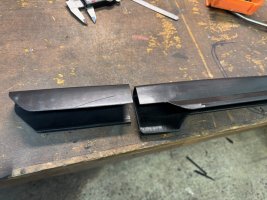
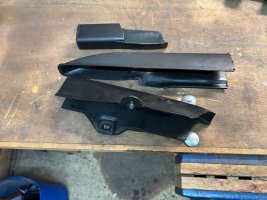
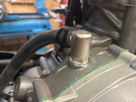
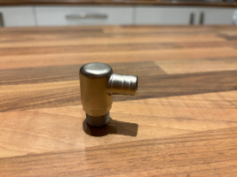
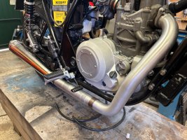
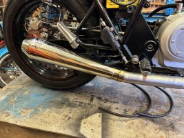
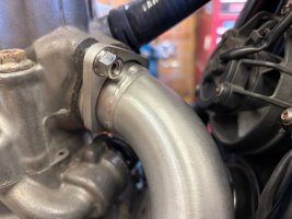
if you want an even "brushed" finish ive had good luck using one of these belt adaptors for an angle grinder with a scotch bright belt. It wraps around the tube and leaves a really nice finish. looks factory.


Some great progress man, I like the finish on the exhaust. Did you make the Fender Stays?
 
Back
Top Bottom