CarbsAndCylinders
Careful With That Axe Eugene
Good to see that your are back at it. I've done nothing on mine, body has pretty much healed up but n/o extra cash.
tattoo said:Into stuff here that I would never dream of attempting!!! Good on ya!!


farmer92 said:It may very well be...
At that price though i'll take the chance. I think as long as i use genuine jets, it should go okay. If it doesn't i'm sure i can pawn them off on someone on kijiji and recoup.
In other news, what was this guys fetish with black crusty tape??
Actually... its all crusty
")
Coincidentally, i hear you're the man to talk to about those ;DSonreir said:Time for a new regulator/rectifier. ;D
johnu said:Hope your wiring ends up looking better than mine ;D
teazer said:I use the same tank for injection oil on the Phat Trakka.
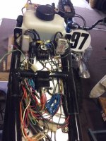
John, what on earth is all that stuff under the seat? Time for a solid state R/R, modern fuse box/power distribution center. Thank goodness winter (assembly time) is coming......
johnu said:Haha, that lot is showing my weak point for sure. I hate auto electrics actually I hate all things electrical. I would dearly love to modernize my system but I would need lots of help!
Sorry for hijacking your thread farmer I hope you wiring ends up better than mine
Kevlar reinforced it would seemCarbsAndCylinders said:Looks like assembly tape...
farmer92 said:Where the shit does red/green and green/white go?
Sonreir said:They come from the alternator.
Back in the day, voltage regulators weren't too awesome of their job. So the engineers often designed the alternators to work at a reduced output level. That is, until you turn the headlight on. Then the alternator would kick out its full potential since the extra wattage was now needed.
When the switch is turned so that the headlight comes on, those two wires will join to once another and complete a partial winding of the alternator, allowing for additional charging capacity.
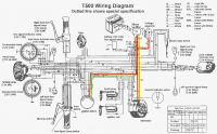
In the attached pic, it might make a bit more sense.
The Y/G wire represents the common side of all the windings. The opposite side of the windings are split into two: The R/G which is always on, and the G/W which is switched on when the headlight comes on.
The G/W and the R/G wires are the same phase, so when the circuit between the two is completed inside the ignition switch, your alternator puts out more juice.
If you're wiring from scratch and using a modern single phase regulator/rectifier (our unit will work well for this), you can splice the G/W and R/G together (completing their circuit) before connecting to the R/R. The G/W and R/G wires from the ignition switch would no longer be needed with this setup.
Sonreir said:They come from the alternator.
Back in the day, voltage regulators weren't too awesome of their job. So the engineers often designed the alternators to work at a reduced output level. That is, until you turn the headlight on. Then the alternator would kick out its full potential since the extra wattage was now needed.
When the switch is turned so that the headlight comes on, those two wires will join to once another and complete a partial winding of the alternator, allowing for additional charging capacity.
In the attached pic, it might make a bit more sense.
The Y/G wire represents the common side of all the windings. The opposite side of the windings are split into two: The R/G which is always on, and the G/W which is switched on when the headlight comes on.
The G/W and the R/G wires are the same phase, so when the circuit between the two is completed inside the ignition switch, your alternator puts out more juice.
If you're wiring from scratch and using a modern single phase regulator/rectifier (our unit will work well for this), you can splice the G/W and R/G together (completing their circuit) before connecting to the R/R. The G/W and R/G wires from the ignition switch would no longer be needed with this setup.