We noticed you are blocking ads. DO THE TON only works with community supporters. Most are active members of the site with small businesses. Please consider disabling your ad blocking tool and checking out the businesses that help keep our site up and free.
You are using an out of date browser. It may not display this or other websites correctly.
You should upgrade or use an alternative browser.
You should upgrade or use an alternative browser.
xxxtra picante...just bought a frickn trainwreck kz750
- Thread starter rich
- Start date
MotorbikeBruno
Over 1,000 Posts
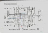
That drawing doesn't seem to load up big enough for me to see what it is.
I'm assuming thats the sidestand switch you have colored in there. One wire looks like it is going to the dash or something, and the second goes to a 3 pin connector? Which leads to another 3 pin connector? (doesn't seem to do anything? )
)
My book only deals with the chain drive models apparently, but electrical should be darn near the same, at least work the same in theory.
I'm assuming thats the sidestand switch you have colored in there. One wire looks like it is going to the dash or something, and the second goes to a 3 pin connector? Which leads to another 3 pin connector? (doesn't seem to do anything?
)My book only deals with the chain drive models apparently, but electrical should be darn near the same, at least work the same in theory.
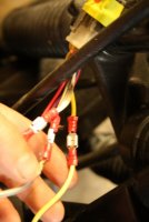
yeah..It seems like purple right wire( next to blue) connects to the engine stop switch and the right hand blue must be an earth to a capped off end ..I think the sidestand switch reroutes the power to the earth when down and to the engine stop switch when up?
the separate switch to the right of the coloured line is the clutch lockout which should lead to the ignition but currently has no clutch lever end...so is lost in the mix somewhere and permanently cutting out power. without colours its a pain to find.
the side stand switch is currently hooked up to a simple wire loop embedded in a connector..the idea being that this will route the powered side back through the system and make it live and therefore switched on
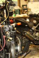
I think Im gonna go through the ignition wiring systematically and freshen up all connectors while adding connectors to the components and rewiring the spaghetti like mess in the middle. e.g new fuse box-new wires to connector to existing ignitor wires.
Avoid the major component wiring but clean up the middle . I should end up with something where Im confident of all the replaced wires- and connectors.
I'll then retest all the components i.e starter- ignitor-coils
and then replace what needs replacing - If everything tests ok and still no spark- I'll buy an ignitor and starter solenoid or coils and replace shit till it works
at least I'll know the clutch lockout and kickstand lockout are not connected to my new set of wiring and the five million three way splices will be gone. The problem is that without spark- every line needs to be tested for resistance and connectivity to know that they work. Its gonna be a big weekend
If anyone has a better plan let me know.
She will ride.
the separate switch to the right of the coloured line is the clutch lockout which should lead to the ignition but currently has no clutch lever end...so is lost in the mix somewhere and permanently cutting out power. without colours its a pain to find.
the side stand switch is currently hooked up to a simple wire loop embedded in a connector..the idea being that this will route the powered side back through the system and make it live and therefore switched on
I think Im gonna go through the ignition wiring systematically and freshen up all connectors while adding connectors to the components and rewiring the spaghetti like mess in the middle. e.g new fuse box-new wires to connector to existing ignitor wires.
Avoid the major component wiring but clean up the middle . I should end up with something where Im confident of all the replaced wires- and connectors.
I'll then retest all the components i.e starter- ignitor-coils
and then replace what needs replacing - If everything tests ok and still no spark- I'll buy an ignitor and starter solenoid or coils and replace shit till it works
at least I'll know the clutch lockout and kickstand lockout are not connected to my new set of wiring and the five million three way splices will be gone. The problem is that without spark- every line needs to be tested for resistance and connectivity to know that they work. Its gonna be a big weekend
If anyone has a better plan let me know.
She will ride.
MotorbikeBruno
Over 1,000 Posts
Rich....the colors are in the right hand bottom of the drawing. In the box. Are they not?
Bruno
Bruno
dp9
Coast to Coast
I'm not a fan of wiring. never have been. Ive taken your approach to it many-a-times, usually with lack luster results (read: some bad connections or accidental grounds). Ive finally become soo fed up with shit not working and taking hours and hours to trouble shoot and ohm things out and "see if it works now. how 'bout now? now?..." I know taking apart the whole wiring harness is a daunting task when looking at it from any starting point, but hear me out. If you take that wiring diagram and remove all the things youre going to leave off the bike, like those two lockout switches, maybe the idiot lights, the two sets of empty accessory leads, etc. you could have close to half the number of wires left. Now take that new diagram and wire the bike from that. Use the right color wires from the harness you just removed and solder all the joints. Yes, it sounds like a pain in the balls, but Its only a solid 8 hrs of work, and youre planning to spend 6 hrs to on it already in the hopes that you fix current problems. Its less time, effort and frustration in the long run. Ive done two kawi 750's this way (twins though). They were plagued with electrical problems initially, and now everything works when I want it to. and I'm not good at wiring.
just my recommendation.
and from the looks of it, this bike is in much better condition than mine was when I got it. you got this. keep the pics and progress coming
just my recommendation.
and from the looks of it, this bike is in much better condition than mine was when I got it. you got this. keep the pics and progress coming
MotorbikeBruno
Over 1,000 Posts
I'm going to have to agree here. If you read the diagram carefully, it tells you what needs power, and where. When I started my wiring thing, I found out those that needed power, got power to them, grounded them and it fired right up. Or I found that it didn't, but I know that there are only a few reasons why, not an entire wiring harness' worth why.
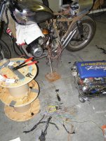
Trust me we've all been there. Exhibit A:
Trust me we've all been there. Exhibit A:
Attachments
MotorbikeBruno said:Rich....the colors are in the right hand bottom of the drawing. In the box. Are they not?
Bruno
the codes are but the diagram is in black and white so everything looks like a zebra= there's nothing saying gr or B/G on the actual page
oki'll agree with everyone and pare down what I can first then re-solder and connect-
stay tuned i appreciate the input-thanks bruno- dp9
MotorbikeBruno
Over 1,000 Posts
Ah! I finally understand what you mean now by the colors...I thought maybe they were on the wires too (like my diagram is!) haha.
More Beer and more cutting needed....heh
More Beer and more cutting needed....heh
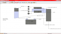
ok guys..dont laugh
heres a dodgy diagram of what I've done after a drunken night with some wiresnips...
I know there's countless things wrong with it - but if you could have a look and point out the obvious issues that'd be great
now that I write this it seems like Ive left of the reg rec- which is clearly the glaring issue where would I put this?
there's currently no fuses and no engine stop switch
get critical for me - suggestions would be great
Attachments
Huckleberry
Active Member
Just reading this thread for the first time - I'm about to do the same thing with a '72 Kawi H1 that's been in storage for 10+ years. I also have zero technical experience and am doing it to learn. Look forward to commiserating but am now officially terrified of what I got myself into.
MotorbikeBruno
Over 1,000 Posts
Dodgy is about right...heh. Just messing with you
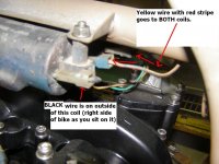
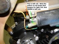
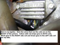
As for coils: You should have one wire that goes to both coils, and then there should be 2 different wires going to each coil. Um well writing this out is harder than I thought. Pictures = 1000 words...sooo I'll go take a pic of my KZ550 should be similar in theory and maybe colors!? I gotta run, I'll post more pics later today or hopefully tomorrow.
Bruno
Attachments
Huckleberry said:Just reading this thread for the first time - I'm about to do the same thing with a '72 Kawi H1 that's been in storage for 10+ years. I also have zero technical experience and am doing it to learn. Look forward to commiserating but am now officially terrified of what I got myself into.
I'm really enjoying it if that counts- the main issue with mine is that the last guy ripped out all the electrics and I've never seen them in the right places..let alone know what they are...Im sure your's will be a lot easier.
i'll be watching your thread
Just enjoy it
MOTHERFUCKER
THE STARTER MOTOR JUST TURNED OVER!!!!!!!!!!!!!!!!!!!!!!!!!!!!!!!!!!!!!!!!!!!!!!!!!!!!!!!!!!!!!!!!!!!!!!!!!!!!!!!!!!!!!!!!!!!!!!!!!!!!!!!!!!!!!!!!!!!!!!!!!!!!!!!!!!!!!!!!!!!!!!!!!!!!!!!!!!!!!!!!!!!!!!!!!!!!!!!!!!!!!!!!!!!!!!!!!!!!!!!!!!!!!!!!!!!!!!!!!!!!!!!!!!!!!!!!!!!!!!!!
I bridged it and it actually turned over briefly
what does this mean lol
I havent thought beyond this point!
shit What do I do
arrghh
seriously though..I guess this means that starter motor is ok- but doesnt really effect anything else
damm its nice to hear a noise from this lump of metal
does it mean the IC ignitor works? or am I bypassing it?
If the ignitor is working then it means the problem lies between it and the coils - wiring is new so It must be a problem with the routing - the coils - the sparkplugs or sparkplug leads
the leads to the starter solenoid from the ignition may also be dodgy
The starter button also still doesnt work \
If the ignitor is not being used would there be enough power to turn over the starter?
so everything is still suspect...hmmmmm
i sprayed some starter stuff in the carbs and nothing happened so no- or not enough spark
so next steps are {suspiciously like the last steps)
1- go back over colour combinations and continuity for Ignitor- sparkplugs
2- check leads to starter solenoid are sound
work out where the ignitor is in the system
How come everybody on here seems to show their work when they are finished and I continuously ask questions about the work itself...I must be bad.
loving it.
well
anither newbie break through...my dodgy wiring diagram is completely frickn wrong- the compliance plate reads KZ-750P
the frame H1
And hidden under an invisible layer of grease and dirt
da da
Z750-P
WRONG MANUAL wrong wires - wrong wrong wrong
here's a good link to wiring diagrams for those who have been reading
http://www.bikechatforums.com/viewtopic.php?p=2322761#2322761
and just in case you thought I was a complete knucklehead (which is true but f you for thinking it)
heres a link to an explanation of why I had difficulty with the model
https://www.z-power.co.uk/merchantmanager/view_information.php?pId=22
and heres five million free manual links
http://www.dansmc.com/shopmanual2.htm
http://warlordsmc.ihoststudio.com/Bike_manuals_2.html


