Father Son 75 CB200T Rise From the Ruins

I want to teach my son that a wise man learns from others. I am completely befuddled how this generation insist on not seeing the pearls they are handed. In the midst of this string
http://www.caferacer.net/forum/project-builds/13818-cb160-turbo-supercharger-build-5.html


Of course there are the usual sages of speed in this string. I think I found a pearl and was wondering your thoughts.

"Would be interesting to see one built with monster 27mm exhaust valves and mildly modified intake tract, and run with a stock cam."-Johnny B

Now I have told Zeke that if a guy has spent 10 grand on a little twin motor then he has a passion. I also asked Zeke if he thought Scubedobeedo was really listening to what was being said.

Now we can buy cb200 heads all day long but it seems to me that Johnny B's proposed scenario will keep the velocity flows up and if you care to read the whole string Teazer as always is providing wisdom. Teazer is wise enough to know you can lead a horse to water but you can't make him drink and Kop knows you can lead an ass with a carrot where you want him to go for entertainment. :)

Ok I am digressing. Now what do you think of Johnny B's proposal and which 27 mm exhaust valve from another bike would you try. I have learned a lot from this string and we are going to try the springs, retainers, and valve guides proposed by Johnny B.

As always you know this horses' ass will try and drink and follow your carrot :) Thanks we appreciate all of you!
 
It would seem to me you'd get more gains by reshaping the ports (specifically the intake).

If empirical tests are showing a loss in power with a hotter cam, the it would seem that the intake ports are not properly sized. A hotter cam will reduce power below a certain RPM, but it should also make it back (and then some) higher up in the revs.

The sizing of the intake ports should be a small as possible without restricting flow. That can be tested simply by hooking up your head to a flow bench (a home made flow bench even works here) and packing playdough into the ports until the flow rate starts to drop (then you know you've gone too far). Additionally, the shape of the intake port will be a contributing factor.

I recall reading that the ideal size for the intake port in a single valve engine is around 80% of the diameter of the valves. Furthermore, the ideal shape will be a D, with the flat side of the port being the port floor. So if your intake valves are 25mm in diameter (I think that's right, but just run with me here if I'm not), then the distance from the port floor to the port ceiling should be around 20mm.

In order to get the ports shaped properly, it isn't always necessary to resort to the addition of metal. If you're building a flat-out top speed racer, then you can expect to have this engine apart a lot of the time. Because of that, you can use methods which may not have as long of a lifespan without concern (because you'll be constantly inspecting them every time the engine is apart). There is a product called Devcon F which is an aluminum epoxy that is very resistant to heat. It can be used to fill in intake ports. It's pretty easy to work with and I recommend it. You can/should end up with something like this (though you will want a smooth transition from manifold to head, so the D shape should be a not be a sharp step):

d_shape.jpg


To increase flow further, you should also grind down any casting marks from the inside of the port ceilings. Additionally, I recommend grinding down the intake valve guides (on the inside of the port) such that they are flush with the port ceiling.

Do all your tests with clay and a flow bench before moving to epoxy and I think you'll be fairly pleased with the results. If you haven't yet, take a look a three (or even five) angle grinds on the valve seats and backcutting the valve, I recommend that as well. Tuliping the valves will help, too, but it's tricky and you need a good machinist to pull it off.
 
Sonreir said:
It would seem to me you'd get more gains by reshaping the ports (specifically the intake).

If empirical tests are showing a loss in power with a hotter cam, the it would seem that the intake ports are not properly sized. A hotter cam will reduce power below a certain RPM, but it should also make it back (and then some) higher up in the revs.

The sizing of the intake ports should be a small as possible without restricting flow. That can be tested simply by hooking up your head to a flow bench (a home made flow bench even works here) and packing playdough into the ports until the flow rate starts to drop (then you know you've gone too far). Additionally, the shape of the intake port will be a contributing factor.

I recall reading that the ideal size for the intake port in a single valve engine is around 80% of the diameter of the valves. Furthermore, the ideal shape will be a D, with the flat side of the port being the port floor. So if your intake valves are 25mm in diameter (I think that's right, but just run with me here if I'm not), then the distance from the port floor to the port ceiling should be around 20mm.

In order to get the ports shaped properly, it isn't always necessary to resort to the addition of metal. If you're building a flat-out top speed racer, then you can expect to have this engine apart a lot of the time. Because of that, you can use methods which may not have as long of a lifespan without concern (because you'll be constantly inspecting them every time the engine is apart). There is a product called Devcon F which is an aluminum epoxy that is very resistant to heat. It can be used to fill in intake ports. It's pretty easy to work with and I recommend it. You can/should end up with something like this (though you will want a smooth transition from manifold to head, so the D shape should be a not be a sharp step):

d_shape.jpg


To increase flow further, you should also grind down any casting marks from the inside of the port ceilings. Additionally, I recommend grinding down the intake valve guides (on the inside of the port) such that they are flush with the port ceiling.

Do all your tests with clay and a flow bench before moving to epoxy and I think you'll be fairly pleased with the results. If you haven't yet, take a look a three (or even five) angle grinds on the valve seats and backcutting the valve, I recommend that as well. Tuliping the valves will help, too, but it's tricky and you need a good machinist to pull it off.
Thanks Sonreir. What head is that off of? What is your choice of valve spring and guides and I understand you have a motor with titanium valves?
 
Sonreir said:
Please let us know how it gets on. Obviously, empirical data trumps armchair theorizing, but I'm wondering if tweaking the timing would result in same final effect?
Sonreir, speaking of arm chair theorizing....I was wondering if this chart was valid and if so, how to read it. I am not sure if the valve lift is correct for our cb200 but I plugged our info that I do know. This is our stock configuration using stock valves 28/25 intake/exhaust and stock 18mm carbs.
 

Attachments

  • image.jpg
    image.jpg
    181.3 KB · Views: 738
This configuration 29mm intake 8mm max lift and 24mm carbs. We estimate this configuration to be:
24mm carbs: 400
Meg Cam and rocker: 600
Head 100
Valves spring etc: 400
Copper gaskets:80
 

Attachments

  • image.jpg
    image.jpg
    180 KB · Views: 1,039
If you compare the two charts you only gain 1 HP for 1200+$$

What is intriguing is John Branson's proposal.

Reshape the intake
28mm intake valves
27mm exhaust valves-100
Port exhaust and guides
Stock cam
Head-100
Serdi cut valves and head-85
Cb160 racing valve springs-42
Titanium keepers and retainers-120
 
I'm really surprised by the intake and exhaust valve sizes. Exhaust valve is usually around 15% smaller and this setup is nearly identical. Seems something is going on here that I don't fully understand.
 
Sonreir said:
I'm really surprised by the intake and exhaust valve sizes. Exhaust valve is usually around 15% smaller and this setup is nearly identical. Seems something is going on here that I don't fully understand.
I have not been able to track John Branson down to ask. Maybe Teazer will comment on his thoughts. John made a comment on another forum and maybe it was just a passing thought but it sounded like common sense to me. The cb200 is "constipated" according to Teazer and John at the exhaust valve. Here is the conversation...
 

Attachments

  • image.jpg
    image.jpg
    225 KB · Views: 286
  • image.jpg
    image.jpg
    126.3 KB · Views: 292
  • image.jpg
    image.jpg
    172.6 KB · Views: 287
What I don't understand is why the exhaust valve is the problem... Traditionally, the exhaust valve is much smaller than the intake valve and in the CB200, it's only a little smaller. It would seem to me that the ratio indicates and intake valve issue rather than exhaust...

It's not that I don't believe these guys, it's just that I'm not ready to sign up to the idea until I know the reasons behind it.
 
Sonreir said:
What I don't understand is why the exhaust valve is the problem... Traditionally, the exhaust valve is much smaller than the intake valve and in the CB200, it's only a little smaller. It would seem to me that the ratio indicates and intake valve issue rather than exhaust...

It's not that I don't believe these guys, it's just that I'm not ready to sign up to the idea until I know the reasons behind it.
i have not seen pictures but it is my understanding by what Teazer has mentioned when we took our head to a car race shop and I posted what they wanted to do...Teazer yanked our bridle like we were going off a cliff. He told us at the time it is the way in which the exhaust is flowing that is causing the turbulence or restriction. He told us at that time not to touch the floor but to raise the roof. He said that keeping the velocity flow
up was paramount.


Google John Branson and I think he is Johnny B...he is a renowned road racer and it was my understanding like Teazer does he has intimate carnal knowledge of the Cb200 head that I should be paying for. But hey I was able to track down my biological father through 5 years worth of research with the wrong phonetics of his name. So I am a firm believer in these two guys...and they are way better men than my Bio dad.
 
Texasstar said:
He told us at that time not to touch the floor but to raise the roof. He said that keeping the velocity flow up was paramount.

Not and uncommon modification with a hemi head. A hemisphere is the ideal shape for a combustion chamber, but it has been abandoned by most manufacturers due the limitations in flow when it comes time to design the ports and situate the valves. The one thing a hemi head does really well, however, is compression, so travelling that road is low hanging fruit.

I'm tempted to go locate a CB200 and open it up, now.

Also... it appears my earlier information was incorrect. The ratio between the intake and exhaust valves is in line with other single valve Honda engines of the day. For some reason, I had it in my head that the exhaust valve was only 1mm smaller in diameter.

Honda CB350/360 Intake Valve - 34mm, Exhaust - 29mm, Ratio: 1.17
Honda CB4500 Intake Valve - 38mm, Exhaust - 33mm, Ratio: 1.15
Honda CB160 Intake Valve - 25mm, Exhaust - 22mm, Ratio: 1.14
Honda CB175/CB200 Intake Valve - 28mm, Exhaust - 24mm, Ratio: 1.17
 
Sonreir said:
Not and uncommon modification with a hemi head. A hemisphere is the ideal shape for a combustion chamber, but it has been abandoned by most manufacturers due the limitations in flow when it comes time to design the ports and situate the valves. The one thing a hemi head does really well, however, is compression, so travelling that road is low hanging fruit.

I'm tempted to go locate a CB200 and open it up, now.

Also... it appears my earlier information was incorrect. The ratio between the intake and exhaust valves is in line with other single valve Honda engines of the day. For some reason, I had it in my head that the exhaust valve was only 1mm smaller in diameter.

Honda CB350/360 Intake Valve - 34mm, Exhaust - 29mm, Ratio: 1.17
Honda CB4500 Intake Valve - 38mm, Exhaust - 33mm, Ratio: 1.15
Honda CB160 Intake Valve - 25mm, Exhaust - 22mm, Ratio: 1.14
Honda CB175/CB200 Intake Valve - 28mm, Exhaust - 24mm, Ratio: 1.17
the Schumann Family in your neck of the woods has a full blown high lift kit using 1.5 over raising it to 29.5 and 25.5 which lowers that to 1.15 I think they like to turn left and drag a foot though...

If we use a 29 and a 27 is 1.07
And a 29.5 and a 27 is is 1.09

A 29 intake is common and reduces velocity flow according to the Kurlon chart. Now what I found intruiging was what teaser said some guys were using 18mm carbs which means the carb is being used to increase velocity and with our velocity stacks now being 120mm I can't wait to see what happens on the dyno at 8k compared to last time. But we may need to recalculate and see if we can catch a pulse at 10k to do the ton. Now I am assuming Kurlon developed the chart above for vintage bikes and seems to be a very bright guy. When I pulled up the chart he had 18mm carbs in it. He said he was running a 30/25 and couldn't get enough lift.

I guess the question now is what is optimum velocity flow through the cb200 head? This is so much fun! That is why he is called Teazer...silence is golden ;)
 
Also every one who has raced the cb175/200 says that it wants to keep pulling past 13k. The limiting factors are heat above 25hp, solved with an oil cooler, and the crank coming apart and the unreliability of the valve train because of the higher lift cams.

I am a firm believer you can do more with less. It seems to me a lower profile cam will allow you to rev higher and generate more hp...
 
The optimum velocity changes with the lift and duration of the cam and the current revs on the motor.
 
Sonreir said:
The optimum velocity changes with the lift and duration of the cam and the current revs on the motor.
Sonreir we really appreciate your time and what you are teaching us. Thank you.
 
No problem, man. I'm learning a few things here, too. This is a great thread.

Also... I should have clarified my statement. Exhaust velocities should be around 300 feet per second at WOT at peak torque.

It's the intake velocities that tend to vary. The reasons for this become apparent when you look at when the cam opens and closes the valves.

Low engine RPMs mean the cylinders are filling less often. A low volume of air through a large volume of intake port means low air velocity. As engine speeds increase, the cylinders fill more often and the volume of air ingested in a given time increases. Your intake port stays the same size, so more volume through the same area means greater velocity.

How this velocity comes into play becomes very important. The ideal time for your intake valve to close will be when the pressure inside the cylinder is equal to the pressure within your intake port. If the valve closes too early, this represents a loss in potential power because it was possible to fit additional fuel and air into the cylinder. If the valve closes too late, your rising piston has created a positive pressure differential between the intake and the cylinder. Unburned fuel/air mix is pushed out of the cylinder and back into the intake port (this is called reversion). This is the trade off when picking a long duration cam; a lot of reversion at low RPMs which results in a drop in torque and power, but you gain at the top end because the intake valve is no longer shutting too soon. Most of the time, calculated horsepower wins out because power increases as revs increase (assuming all other variables hold constant).

One other variable to balance in this equation is the intake velocity and flow. Traditionally, velocity and flow are the opposites of one another. Velocity is attained by reducing the size of the intake, whereas flow is increased by providing intake ports that have a larger cross sectional area and/or better shape. Counter intuitively, you can actually increase overall flow with a increase in velocity as all of the air molecules will tend to travel in the same direction rather than floating around a bumping into each other (as occurs with overly large intakes). This same theory is what drives the design of velocity stacks.

The real reason for seeking a high velocity intake goes back to cam durations, however. Traditional four stroke engine theory has us believe that there are four distinct cycles of operation in the engine: Intake, Compression, Power, Exhaust. I subscribe to the idea that this is overly simplistic when it comes time to build for power.

We really need to blur the lines between the Exhaust, Intake, and Compression strokes. The reason for this blurring is that the intake valve is open for all of the Intake stroke, but also for part of the Exhaust and Compression strokes.

When the intake valve begins to open, the piston is still rising and exhaust gases are still leaving the cylinder. The reason for the early opening of the intake valve is this: Low lift flow is nearly non-existent, so by opening the intake valve early, we can ensure we have the flow we need when we want it. How quickly we transition from a low flow to high flow situation has everything to do with velocity, however. The speed at which a fluid (air is a fluid) travels and accelerates is directly related to the difference in pressure between the two locations (this is called Delta P). This means we get the best fill rate of the cylinder when the pressure within the cylinder is low and the pressure within the intake is high. This pressure within the intake port is created by a high velocity charge impacting a suddenly-closed intake valve from the previous cycle (think about a line of joggers following one another in a straight line and the lead runner runs into a wall; all the guys in the front are gonna get squished and this is the same thing that happens to the air in the intake). So this high velocity allows us to open the intake sooner and start the process sooner. As RPMs increase, we have less and less time to perform this operation, so every microsecond counts. Like racing, sometimes your overall placement will come down to your start.

Now we're on to the Intake stroke. The piston is now descending and the intake valve is now open a significant amount. High velocity is still of benefit, but this stroke is all about flow. The lift of your cam will play a significant role in this cycle. Delta P quickly shifts as the piston descends and the volume within the cylinder increases. This causes low pressure within the cylinder (when compared with atmospheric). As the air enters the cylinder, the air exits the intake, and so the differential begins to equalize and more air is pulled (by gravity) into the intake tract to replace the air entering the cylinder. This action increases your upstream intake velocity which will help the stroke.

As the Intake stroke comes to an end and the Compression stroke begins, the intake valve is still open. The reason for this has EVERYTHING to do with intake velocity. The volume in the cylinder is now decreasing as the piston rises. This causes a corresponding increase in pressure inside the cylinder which can only be overcome by pressure within the intake (which comes in the form of velocity). So long as you have greater pressure within the intake than you do within the cylinder, you should hold the intake valve open so you can keep stuffing in more fuel and air. The higher the intake velocity, the longer you can hold the valve open (or partway open). It's like stuffing suitcases into the back of your car; you can pack in many as you want so long as you have enough strength to close the trunk when you're done. ;)

So here are the variables you're working with, listed out without too much flourish:
*The engine will want to ingest a certain amount of air at a given RPM due solely to the displacement
*The velocity at which the air enters the engine is governed by the size and shape of the intake ports and valves, any upstream obstacles such as the carbs and intake filters, and the ability of the engine to dispel exhaust gases from the previous cycle
*Because the intake design is static (excepting CV carbs), intake velocity changes as RPMs change
*The camshaft controls when the valves open and close (and how wide the valves open) and this is usually static as well
*Because damn near everything is static except velocity, a cam works best at a specific RPM band
*Changing any of the above variables will affect all of the others, but it usually holds true that a cam of higher duration and higher lift will provide better top end horsepower so long as the intake and exhaust ports/valves are not a limiting factor (either by having too little flow or not enough velocity)
 
Sonreir said:
No problem, man. I'm learning a few things here, too. This is a great thread.

Also... I should have clarified my statement. Exhaust velocities should be around 300 feet per second at WOT at peak torque.

It's the intake velocities that tend to vary. The reasons for this become apparent when you look at when the cam opens and closes the valves.

Low engine RPMs mean the cylinders are filling less often. A low volume of air through a large volume of intake port means low air velocity. As engine speeds increase, the cylinders fill more often and the volume of air ingested in a given time increases. Your intake port stays the same size, so more volume through the same area means greater velocity.

How this velocity comes into play becomes very important. The ideal time for your intake valve to close will be when the pressure inside the cylinder is equal to the pressure within your intake port. If the valve closes too early, this represents a loss in potential power because it was possible to fit additional fuel and air into the cylinder. If the valve closes too late, your rising piston has created a positive pressure differential between the intake and the cylinder. Unburned fuel/air mix is pushed out of the cylinder and back into the intake port (this is called reversion). This is the trade off when picking a long duration cam; a lot of reversion at low RPMs which results in a drop in torque and power, but you gain at the top end because the intake valve is no longer shutting too soon. Most of the time, calculated horsepower wins out because power increases as revs increase (assuming all other variables hold constant).

One other variable to balance in this equation is the intake velocity and flow. Traditionally, velocity and flow are the opposites of one another. Velocity is attained by reducing the size of the intake, whereas flow is increased by providing intake ports that have a larger cross sectional area and/or better shape. Counter intuitively, you can actually increase overall flow with a increase in velocity as all of the air molecules will tend to travel in the same direction rather than floating around a bumping into each other (as occurs with overly large intakes). This same theory is what drives the design of velocity stacks.

The real reason for seeking a high velocity intake goes back to cam durations, however. Traditional four stroke engine theory has us believe that there are four distinct cycles of operation in the engine: Intake, Compression, Power, Exhaust. I subscribe to the idea that this is overly simplistic when it comes time to build for power.

We really need to blur the lines between the Exhaust, Intake, and Compression strokes. The reason for this blurring is that the intake valve is open for all of the Intake stroke, but also for part of the Exhaust and Compression strokes.

When the intake valve begins to open, the piston is still rising and exhaust gases are still leaving the cylinder. The reason for the early opening of the intake valve is this: Low lift flow is nearly non-existent, so by opening the intake valve early, we can ensure we have the flow we need when we want it. How quickly we transition from a low flow to high flow situation has everything to do with velocity, however. The speed at which a fluid (air is a fluid) travels and accelerates is directly related to the difference in pressure between the two locations (this is called Delta P). This means we get the best fill rate of the cylinder when the pressure within the cylinder is low and the pressure within the intake is high. This pressure within the intake port is created by a high velocity charge impacting a suddenly-closed intake valve from the previous cycle (think about a line of joggers following one another in a straight line and the lead runner runs into a wall; all the guys in the front are gonna get squished and this is the same thing that happens to the air in the intake). So this high velocity allows us to open the intake sooner and start the process sooner. As RPMs increase, we have less and less time to perform this operation, so every microsecond counts. Like racing, sometimes your overall placement will come down to your start.

Now we're on to the Intake stroke. The piston is now descending and the intake valve is now open a significant amount. High velocity is still of benefit, but this stroke is all about flow. The lift of your cam will play a significant role in this cycle. Delta P quickly shifts as the piston descends and the volume within the cylinder increases. This causes low pressure within the cylinder (when compared with atmospheric). As the air enters the cylinder, the air exits the intake, and so the differential begins to equalize and more air is pulled (by gravity) into the intake tract to replace the air entering the cylinder. This action increases your upstream intake velocity which will help the stroke.

As the Intake stroke comes to an end and the Compression stroke begins, the intake valve is still open. The reason for this has EVERYTHING to do with intake velocity. The volume in the cylinder is now decreasing as the piston rises. This causes a corresponding increase in pressure inside the cylinder which can only be overcome by pressure within the intake (which comes in the form of velocity). So long as you have greater pressure within the intake than you do within the cylinder, you should hold the intake valve open so you can keep stuffing in more fuel and air. The higher the intake velocity, the longer you can hold the valve open (or partway open). It's like stuffing suitcases into the back of your car; you can pack in many as you want so long as you have enough strength to close the trunk when you're done. ;)

So here are the variables you're working with, listed out without too much flourish:
*The engine will want to ingest a certain amount of air at a given RPM due solely to the displacement
*The velocity at which the air enters the engine is governed by the size and shape of the intake ports and valves, any upstream obstacles such as the carbs and intake filters, and the ability of the engine to dispel exhaust gases from the previous cycle
*Because the intake design is static (excepting CV carbs), intake velocity changes as RPMs change
*The camshaft controls when the valves open and close (and how wide the valves open) and this is usually static as well
*Because damn near everything is static except velocity, a cam works best at a specific RPM band
*Changing any of the above variables will affect all of the others, but it usually holds true that a cam of higher duration and higher lift will provide better top end horsepower so long as the intake and exhaust ports/valves are not a limiting factor (either by having too little flow or not enough velocity)
Let me see if i can digest part of what you just told me...so what a charts above should look like is different velocities for each cycle..then the optimum velocity changes as we go through the motor cycles (bad joke) we should have a higher velocity through the carb, slightly slower through the intake valve and slightly slower through the exhaust valve??? Because there is a certain amount of resistance that creates velocity. To much or too little in each cycle creates a problem.
 
Mostly right. Velocities will generally increase the closer you get to the combustion chamber. Slower through the stacks and carbs, gaining speed through the intake port, and very quick past the intake valve. Usually between 60 and 80 fps through the carbs and as high as .5 mach past the intake valves (and even faster still in more modern, multivalved engines).

Your job as an engine builder is to create an environment that maximizes velocity without significantly impacting flow (some will argue for not impacting flow at all, but I'm usually happy to trade some flow for some velocity in most situations) and then selecting the cam profile that will make the best use of that flow/velocity combination given your requirements for the engine.
 
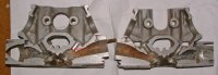
I don't know if you have seen this before but maybe its worth sharing for your analysis. It is however a Vertical 175 head, not a 200.
 

Attachments

  • V175-SplitHeadView.jpg
    V175-SplitHeadView.jpg
    323.1 KB · Views: 304
Back
Top Bottom